Ammonia as Effective Hydrogen Storage: A Review on Production, Storage and Utilization


1
Institute of Industrial Science, The University of Tokyo, Tokyo 153-8505, Japan
2
Mechanical Engineering Department, Engineering Faculty, Sebelas Maret University, Surakarta 57126, Indonesia
3
Departemen Kimia, Universitas Pendidikan Indonesia, Bandung 40154, Indonesia
*
Author to whom correspondence should be addressed.
Energies 2020, 13(12), 3062; https://doi.org/10.3390/en13123062
Submission received: 18 March 2020
/
Revised: 5 June 2020
/
Accepted: 10 June 2020
/
Published: 12 June 2020
(This article belongs to the Special Issue Advances in Hydrogen Energy)
Abstract
:Ammonia is considered to be a potential medium for hydrogen storage, facilitating CO2-free energy systems in the future. Its high volumetric hydrogen density, low storage pressure and stability for long-term storage are among the beneficial characteristics of ammonia for hydrogen storage. Furthermore, ammonia is also considered safe due to its high auto ignition temperature, low condensation pressure and lower gas density than air. Ammonia can be produced from many different types of primary energy sources, including renewables, fossil fuels and surplus energy (especially surplus electricity from the grid). In the utilization site, the energy from ammonia can be harvested directly as fuel or initially decomposed to hydrogen for many options of hydrogen utilization. This review describes several potential technologies, in current conditions and in the future, for ammonia production, storage and utilization. Ammonia production includes the currently adopted Haber–Bosch, electrochemical and thermochemical cycle processes. Furthermore, in this study, the utilization of ammonia is focused mainly on the possible direct utilization of ammonia due to its higher total energy efficiency, covering the internal combustion engine, combustion for gas turbines and the direct ammonia fuel cell. Ammonia decomposition is also described, in order to give a glance at its progress and problems. Finally, challenges and recommendations are also given toward the further development of the utilization of ammonia for hydrogen storage.
1. Introduction
The adoption of fossil fuels in conventional energy systems has led to the increase of the concentration of greenhouse gases (GHGs) in the atmosphere and the rise of ocean levels [1]. Being aware of this reality, recently, the adoption of renewable energy has increased rapidly due to its low environmental impacts. In addition, the massive deployment and the maturity of technology have made renewable energy economic and competitive against conventional fossil fuels. It is expected that a clean and CO2-free energy system can be realized to improve the quality of human life. The Conference of Parties 21 (COP21), held in 2015, issued the world commitments to the mitigation of climate change and keeping the increase of the global average temperature below 2 °C higher than the pre-industrial level [2]. Moreover, the Marrakech Partnership for Global Climate Action has strongly promoted collective striving for the 1.5 °C temperature goal through mutual collaboration among governments, regions, businesses and investors [3].
Liberalization and decentralization in the energy sector has also opened up the opportunity to the customers to behave simultaneously as energy producer and consumer. The fluctuating demand and supply sides in the future energy system also require an effective adoption of secondary energy sources (energy carriers) which can be effectively and economically produced, stored and utilized. The future energy system is expected to be able to facilitate the optimum utilization of local energy resources (especially renewable energy) [4], reduction of global GHG emission, improvement of urban environmental quality and creation of industrial activities focusing the energy sector toward a sustainable economy [5].
Hydrogen (H2) is one of the secondary energy sources which produces no GHG by-products during its utilization, because the oxidation of hydrogen generates water (H2O). It is the most abundant element in the universe (more than 90% of the total available atoms), the lightest element (molecular weight of 2.016) and non-toxic [6]. Hydrogen has significantly higher gravimetric energy density (120 MJ/kg) compared to other conventional fuels, such as gasoline (44 MJ/kg). In addition, hydrogen can be produced from various kinds of primary energy sources, including renewables and non-renewables. Many technological routes are available, including thermochemical routes (gasification, chemical looping, reforming), biochemical routes (fermentation) and electrolysis [7]. Furthermore, the utilization of hydrogen as an energy source can also be performed via various technologies, such as fuel cells, combustion and mixing with other fuels. However, hydrogen suffers a disadvantage in its volumetric energy density, which is only 3 Wh/L, leading to difficulties in its storage. Hydrogen storage is the key enabling technology which will lead to the successful deployment of hydrogen, including its economic sustainability.
There are several key parameters in the selection of hydrogen storage methods and materials, including: (a) gravimetric and volumetric hydrogen densities, (b) energy efficiency, (c) refueling time, (d) durability, (e) cost, (f) standards, (g) technology maturity and (h) life-cycle and efficiency analysis [8]. Energy efficiency deals with the energy consumed during both the storage and release of hydrogen to and from its storage states or hydrogen storage materials. Furthermore, durability is correlated to its lifetime, especially in case of reversible hydrogen storage materials. Standards for the storage systems and interface are required in order to facilitate the implementation of the storage technology, as well as safety and public acceptance. The successful development of hydrogen storage is crucial for the future of hydrogen economy [9,10].
In order to store hydrogen effectively, different hydrogen storage technologies have been studied and developed. These include compressed and liquefied hydrogen, liquid organic carriers [11], metal hydrides [12,13], methanol (CH3OH) and ammonia (NH3). Hydrogen storage covers both mobile and stationary systems. Compressed hydrogen is the simplest way to store hydrogen, although its hydrogen density is low (42.2 kg-H2/m3 at 69 MPa). Compressed hydrogen requires high pressure to effectively store the gaseous hydrogen. In the case of a hydrogen vehicle, a high pressure tank of about 70 MPa is currently required in order to store the hydrogen to achieve a similar driving range to conventional vehicles. Moreover, as hydrogen is a very light and small element, leakage from high pressure can easily occur, in addition to the problem related to hydrogen embrittlement. Liquid hydrogen is also considered promising and efficient as a hydrogen storage option, because it has higher hydrogen density (70.8 kg-H2/m3), which is about 800 times that of uncompressed hydrogen (0.08988 kg/m3 at standard temperature and pressure (STP)), as well as high purity. However, in order to bring hydrogen into the liquid phase, refrigeration to a very low temperature (−253 °C) is required, leading to high energy consumption. Moreover, due to this cooling requirement, liquid hydrogen is not preferred for long term storage or long distance of transportation, because the energy input needed to keep the temperature very low is also intensive. Another problem of liquid hydrogen is the conversion of ortho-hydrogen (where the spins of both nuclei are in the same direction) to para-hydrogen (where the spins of both nuclei are in opposite directions) [14]. As this isomer conversion is exothermic, the generated heat causes the boil-off phenomenon, in which a part of liquid hydrogen is evaporated into a gaseous form.
Solid-state systems are also considered a potential hydrogen storage method. They can reversibly adsorb and release hydrogen. The storage of hydrogen occurs by two different methods: physisorption and chemisorption [15,16]. In the former, hydrogen molecules are adsorbed on the surface of an adsorbent (storage medium) due to the intermolecular force that exists between the adsorbate (hydrogen) and adsorbent. Physisorption hydrogen storages include carbon nanotubes, activated carbon, zeolites and metal-organic frameworks (MOFs). These materials are advantageous in terms of their reversibility and relatively fast kinetics. However, they have several disadvantages, including low hydrogen storage (lower than 5 wt% at room temperature) and their requirement of low temperatures for larger hydrogen storage capacities [17,18]. On the other hand, in chemisorption hydrogen storage, hydrogen chemically reacts with solids, producing hydrides. These hydrides can be categorized into metal, complex and chemical hydrides. Recently, various complex hydrides have been developed, including NaAlH4, Mg(NH2)2-LiH. Although these materials show high hydrogen density (up to 10 wt%), their hydrogenation and dehydrogenation are very complex and their reversibility is relatively low [19,20]. In addition, these processes also lead to the decrease of energy efficiency, especially the dehydrogenation process, which is generally endothermic.
Methanol is also a promising candidate for hydrogen storage, as well the utilization of CO2 via hydrogenation [21]. The adoption of methanol is strongly correlated with the idea of power-to-product (P2X), which utilizes surplus electricity to produce chemical fuels. Hydrogen can be released from methanol through thermolysis, steam reforming and partial oxidation [21]. However, the adoption of methanol to store hydrogen leads to environmental problems in the utilization site because of the release of CO2 when methanol is directly utilized or decomposed. This leads to a non CO2-free energy system. In addition, the separation of CO2 is also energy intensive. The established CO2 separation based on absorption using amine solution consumes approximately 1.1 kWh/kg-CO2 [22].
On the other hand, ammonia is highly valued as a potential hydrogen storage option. It has high hydrogen density (17.8 wt%), as well as high flexibility in its utilization, including mobile and stationary applications. Due to its stability for long-term storage and transportation, ammonia can fulfill the demand to store the energy in time (stationary energy storage) and in space (energy export and import) [23]. Ammonia can be utilized by extracting its stored hydrogen or directly utilized as fuel. Ammonia is currently adopted as an agricultural fertilizer, refrigerant gas and in the manufacture of explosives, pesticides and other chemicals. Therefore, the infrastructures to produce, store, transport and utilize ammonia have been globally established [24], leading to its proven economic performance. In addition, regulations and procedure for ammonia handling have been established well in the world. The ammonia economy has been investigated in numerous studies, including studies of islanded systems [25], process modeling and fertilizer production using renewable energy [23]. However, for applications in the energy sector, ammonia still faces various challenges, including its properties, conversion technologies and possible environmental problems following its utilization.
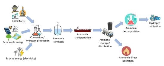
Figure 1 shows the possible routes for the production and utilization of ammonia. Ammonia can be produced from both fossil fuels and renewable energy sources. These primary energy sources are then converted to ammonia through several processes, including pre-treatment, conversion and synthesis. In addition, the surplus electricity can also be converted to hydrogen [26], which is further converted to ammonia, leading to the application of power-to-ammonia. The produced ammonia is then stored, transported and distributed to the users for its utilization. Numerous countries in the world have a strong motivation to utilize ammonia as one of key players in future energy system. Therefore, these countries have tried to set the future road map, as well as developing the technologies to realize the plan. Japan has clearly decided its plan for ammonia adoption. The ammonia supply chain in the energy sector has been targeted for realization by 2030 [27]. In the beginning, 300 kW-class gas turbines will be tested until the end of 2020. Moreover, other movements to utilize ammonia, including advanced combined cycles, direct ammonia-fueled fuel cells and the co-firing of ammonia at existing coal-fired power plants, have also been started [28]. Australia has also accelerated research and development programs for ammonia utilization in order to store the produced hydrogen by the country and then export it to other countries [29]. Similar research motivation to push the adoption of ammonia has also been shown by the UK [30] and Germany [31]. In addition, the electricity generation and industrial sectors have been targeted as the first projected market.
This work reviews potential technologies, covering the production, storage and utilization of ammonia, as well as its important role in the energy system. Section 2 describes the characteristics of ammonia, especially in terms of its advantages and disadvantages as a hydrogen storage mechanism. Section 3 explains several possible ammonia production technologies, including conventional and advanced production systems. Section 4 describes potential ammonia storage methods, especially liquid ammonia. Furthermore, the utilization of ammonia is described in Section 5, especially direct utilization technologies. The decomposition of ammonia and separation of the hydrogen gas stream are also described in this section. Challenges and recommendations related to the adoption of ammonia are discussed in Section 6. Finally, Section 7 concludes the points reviewed in this work.
2. Characteristics of Ammonia
2.1. Physical Properties
Ammonia is alkaline, colorless and has a relatively strong odor. Table 1 shows the detailed parameters of the physical properties of ammonia. From techno-economic analysis, ammonia is considered to be the least expensive fuel compared to other conventional fuels, such as gasoline, natural gas, liquefied petroleum gas (LPG), methanol and hydrogen [32]. In addition, liquid ammonia has a relatively high volumetric energy density, 12.7 MJ/L, which is higher than liquid hydrogen (8.49 MJ/L) and compressed hydrogen (4.5 MJ/L at pressure of 69 MPa and temperature of 25 °C). The boiling temperature of ammonia is −33.4 °C at atmospheric pressure. Furthermore, ammonia has a significantly higher combustion heat, 11.2 MJ/L, compared to liquid hydrogen (8.58 MJ/L).
Gaseous ammonia can dissipate very quickly in the air under atmospheric conditions due to its lighter density than the air (0.769 kg/m3 compared to 1.225 kg/m3 at STP), minimizing explosion and fire risks in case of leakage. Furthermore, as ammonia has a higher auto ignition temperature (650 °C) than hydrogen (520 °C), ammonia has a lower risk of fire than hydrogen. The apparent toxicity (vapor pressure relative to toxicity at atmospheric temperature) of liquid ammonia is about three orders of magnitude higher than gasoline and methanol. This is due to the phenomenon that liquid ammonia has an immediately dangerous to life or health (IDLH) concentration of about 300 ppm, but its vapor pressure is relatively high; 8.58 × 10² kPa at 20 °C [33].
The challenges faced by ammonia include its narrow flammability range, which is 15.15–27.35% in dry air and 15.95–26.55% in 100% relative humidity air. Hence, it is usually considered to be non-flammable during its storage and transportation. In addition, as ammonia has nitrogen as its main component, the utilization of ammonia, especially in high temperatures, potentially leads to NOx formation. Therefore, the combustion management of ammonia is crucial. Moreover, as ammonia is categorized as a toxic chemical, it is important to carry out appropriate hazard management in order to mitigate its danger to humanity and the environment.
2.2. Hydrogen Storage Performance
Table 2 lists the characteristics comparison of hydrogen storage methods, including compressed hydrogen, liquid hydrogen, methanol and liquid ammonia. Liquid ammonia is able to store hydrogen in volumes much higher (121 kg-H2/m3) than liquid hydrogen (70.8 kg-H2/m3), which is about 1.7 times as high. Liquid ammonia can be stored at relatively low pressure (0.99 MPa at a temperature of 25 °C), which is significantly lower than that of compressed hydrogen. However, in terms of physical density, liquid ammonia has the higher density (600 kg/m3) than compressed and liquid hydrogen, leading to heavier storage and transportation.
Methanol is a strong competitor for the storage of hydrogen. It has higher energy density than ammonia (20.1 MJ/kg compared to 18.6 MJ/kg). However, it has both lower gravimetric and volumetric hydrogen contents than ammonia (12.5 wt% and 99 kg-H2/m3 compared to 17.8 wt% and 121 kg-H2/m3, respectively) [36]. As methanol involves CO2 in its synthesis, its utilization and decomposition also release CO2, leading to the environmental concerns. Methanol reformation also leaves the problem of the production of carbon monoxide (CO), which can poison most of the catalysts adopted in fuel cells, and hence shortens the life time of the fuel cell [37].
To release the hydrogen from ammonia, a relatively huge amount of energy is consumed (30.6 kJ/mol-H2). On the other hand, the regasification of liquid hydrogen only consumes very low energy (0.907 kJ/mol-H2). Therefore, ammonia decomposition is a challenging task, especially in terms of total energy efficiency in the utilization of ammonia. The decomposition of ammonia must be followed by hydrogen separation in the case that a high purity of hydrogen is demanded at the utilization site. On the other hand, compressed and liquid hydrogen can deliver highly pure hydrogen.
3. Ammonia Production
Currently, about 200 Mt/y of ammonia is manufactured globally [40], making it the world’s second most commonly produced chemical after sulfuric acid (H2SO4). Similarly to hydrogen, ammonia can be produced from different primary energy sources, including biomass, coal, natural gas, solar, wind, geothermal, hydro and nuclear sources. Ammonia can be produced through different conversion technologies: thermochemical, electrochemical, photochemical and plasma [41]. However, with the consideration of technological feasibility and total energy efficiency [42,43], in this work, three main conversion technologies (Haber–Bosch, electrochemical and thermochemical cycle processes) are described. Furthermore, recent trends in the development of enhanced systems in order to improve the total energy efficiency during ammonia production are also described.
3.1. Conventional Ammonia Production (Haber–Bosch Process)
The currently adopted ammonia production process basically employs the system invented by Fritz Haber and Carl Bosch about 100 years ago [40]. Therefore, this system is well known as Haber–Bosch process. About 85% of total production of ammonia worldwide is produced by this process [44]. The ammonia synthesis occurs according to reaction (1).
3 H2 + N2 ⇋ 2 NH3 ΔH°27 °C = −46.35 kJ/mol
Ammonia synthesis is an exothermic reaction (negative enthalpy change), and it occurs spontaneously at low temperatures (negative entropy change). Although it is favored at room temperature, the reaction rate at which the reaction occurs at room temperature is too slow to be applicable for at an industrial scale. In order to increase the kinetics of the reaction to achieve the targeted conversion rate, high pressure and temperature are required. To effectively synthesize ammonia from its main components (hydrogen and nitrogen), the reaction should be performed at a relatively high temperature and pressure of 400–500 °C and 10–30 MPa, respectively, with the assistance of an iron-based catalyst. This condition is demanded due to the high dissociation energy (941 kJ/mol) of triple-bonded nitrogen. However, to bring the reaction under this high temperature and pressure, about 30 MJ/kg-NH3 of energy is required [45].
The production of ammonia from natural gas is conducted by reacting methane (natural gas) with steam and air, coupled with the subsequent removal of water and CO2. The products of this process are hydrogen and nitrogen, which are the feedstock for the main ammonia synthesis. During the process, the removal of sulfur and other impurities is important, because they can reduce and damage the performance of the catalyst during synthesis. In the ammonia synthesis process, both nitrogen and hydrogen are compressed to relatively high pressure to be fed to the synthesis reactor, where the catalyst is immersed inside. The produced ammonia, together with the unreacted hydrogen, argon and other impurities, is then cooled down for ammonia condensation in order to separate the ammonia from the other gases. The unreacted hydrogen and nitrogen are then recycled back and mixed together with the new feedstock. To avoid a build-up of impurities, such as argon, a small part of the gases is purged from the process. Ammonia synthesis produces a small amount of heat, which is released from the reactor; therefore, it can be recovered and utilized for other processes, such as steam and power generation. In general, about 88% of hydrogen’s calorific value can be conserved [46].
Another challenge in the Haber–Bosch process is its low conversion rate; therefore, the process must be recycled to achieve the expected production flow rate. However, at pressure of 30 MPa, the conversion rate from the reaction is still low, no more than 25% [47]. This stream recirculation causes some problems, including the need for an additional recirculation system and a larger reactor, leading to high investment and operation costs.
When hydrogen is produced via water electrolysis, nitrogen can be supplied via air separation. Air separations for nitrogen production can be conducted via membrane, cryogenic, absorption and adsorption technologies [48]. For large scales, cryogenic separation is considered more economical than other methods. In addition, cryogenic air separation could produce a high purity of products [49].
The energy consumed during ammonia production, including conversion from primary sources, typically ranges from about 28 to 37 GJ/t [44]. An ammonia production system from any primary source, such as natural gas, is considered complex, as it includes many combined processes. Figure 2 shows the schematic diagram of conventional ammonia production from natural gas. The system consists of different processes: steam reformation, the water–gas shift reaction, CO2 removal, syngas purification, and ammonia synthesis and separation. Therefore, efforts to reduce the total energy consumption require the improvement of the whole process involved. Due to high energy intensity of ammonia production, ammonia synthesis emits a total of 289.8 Mt-CO2 annually [25], which is almost 0.93% of global CO2 emissions [50].
Focusing on the Haber–Bosch process, many efforts to reduce its extreme conditions have been carried out. They include the introduction of an extra component in order to inhibit the catalysis and the alteration of geometry and electronic nature of the reacting components in order to optimize the energetics of catalysis [51]. Ru-based catalysts can basically facilitate ammonia synthesis under mild conditions (at a temperature of 300–450 °C and pressure of 4–15 MPa), which is significantly lower than the conditions required for iron-based catalysts. However, Ru-based catalysts are expensive and suffer from hydrogen poisoning [52,53]. Alkaline earth metal oxides and hydroxides have been identified as promoters to improve the catalytic performance of Ru-based catalysts [54]. Several electrides (crystals in which electrons serve as anions), such as Ca2N:e−, which can be deposited in Ru nanoparticles have the potential to facilitate ammonia synthesis at 200 °C [55]. Transition metals (TM) can also improve synthesis performance, including lowering the pressure and temperature. This is due to the existence of scaling relations between the transition-state energy required for the dissociation of nitrogen and the adsorption energy of all the intermediates [56,57]. Furthermore, Kawamura and Taniguchi [58] have tested sodium melt as a catalyst for ammonia synthesis. By using this type of catalyst, the synthesis could be carried out at reaction temperatures of 500–590 °C and atmospheric pressure. However, further analysis and experimentation are required to bring this method to the level of being applicable.
3.2. Electrochemical Processing
Although electrochemical processing is significantly under-developed compared to the Haber–Bosch process, it is expected to realize higher energy performance. The energy consumed by this process is about 20% lower than the Haber–Bosch process [59]. Figure 3 shows the schematic flow diagram of electrochemical ammonia synthesis. The process is considered simple; therefore, its application is considered to potentially reduce system configuration and control complexity. In addition, the investment cost can be lower compared to currently adopted ammonia synthesis systems.
The reactions at both cathode and anode in proton conducting cells are shown in reactions (2) and (3), respectively. The reactions at each cathode and anode are basically reversible.
N2 + 6 H+ + 6 e− ⇌ 2 NH3
3 H2 ⇌ 6 H+ + 6 e−
Four different types of electrolytes are currently available: (a) liquid electrolytes, (b) molten salt, (c) composite membranes and (d) solid state electrolytes. Liquid electrolytes can operate under atmospheric temperature and pressure [60]. There are some potential liquid electrolytes, including LiClO4 (0.2 M) in tetrahydrofuran [60], LiClO4 in ionic liquid, LiClO4 in H2SO4 and Li2SO4 in H2SO4 [61]. Ammonia production of 3.68 × 10⁻¹⁰ mol/cm2·s could be obtained, while the system efficiency can reach about 58%, indicating that about 58% of the current supplied to the system is converted into ammonia. However, the research related to this issue is still limited to lab experiments, in small dimensions of cells and limited operation times [41].
A molten salt type electrolyte is generally operated at a temperature range of 300–500 °C [62]. There are some potential chemicals for use as electrolytes, such as LiCl, KCl and CsCl, with dissolved Li3N [63]. The reported ammonia production rate is 3.3 × 10⁻⁹ mol/cm2·s, and the efficiency is about 72%. Moreover, the system with composite electrolytes also includes solid electrolytes, which are combined with low melting salt, and have an operating temperature of 300–700 °C. The electrolytes comprise the main ionic conducting phase and an additional phase that is attached to the main phase to improve the electrical, mechanical and thermal properties [33]. As the representative of composite electrolytes, alkali metal carbonate (such as LiCO3) and oxide (such as LiAlO2) and CeO2 doped with Sm2O3 have shown the expected properties, including oxygen ion, carbonate ion and proton conductivity [64]. In addition, Amar et al. [64] have tested mixed Na, K and Li carbonates, in addition to the LiAlO2, as the electrolyte. They obtained an ammonia production rate of 2.32 × 10⁻¹⁰ mol/cm2·s at a temperature of about 400 °C. The system with solid electrolytes generally operates in very wide operating temperatures, from room temperature to about 800 °C. There are different materials which can be included in this type of electrolyte. These include perovskites (such as cerate and zirconate) [65], fluorites (such as doped zirconia, ceria and thoria), pyrochlores (such as calcium doped lanthanum zirconate) and other materials (including brownmillerite, eulytite and monazite) [33]. The challenges of this type of electrolyte include their structural stability and the high sintering temperature (up to 1700 °C) which is required to achieve a high density. By adopting this kind of solid state electrolyte, the ammonia production rate of 3.1 × 10⁻⁹ mol/cm2·s could be achieved under the temperature of 570 °C, with an efficiency of about 75% [33,66].
3.3. Thermochemical Cycle of Ammonia Production
As an alternative process for ammonia production, a process employing the thermochemical cycle has been developed [67]. The system consists of two circulated processes: reduction (nitrogen activation) and steam-hydrolysis (ammonia formation). Both reactions are summarized as follows:
Al2O3 + 3C + N2 → 2 AlN + 3 CO ΔH°25 °C = 708.1 kJ/mol
2AlN + 3 H2O → Al2O3 + 2 NH3 ΔH°25 °C = −274.1 kJ/mol
Figure 4 shows the schematic diagram of the thermochemical cycle of ammonia production. The primary energy sources are pre-treated and converted to carbon before being fed to the thermochemical cycle process. In the first reduction process (reaction (4)), the AlN is produced through the carbothermal reduction of Al2O3 and nitrogen. This reaction is endothermic and occurs under a reaction temperature of about 1500 °C. Moreover, in the second reaction, which is steam-hydrolysis (reaction (5)), the AlN produced in the first reduction process is reacted with steam (H2O) producing Al2O3. The produced Al2O3 from this second reaction is then circulated to the first reduction process. Detailed reaction kinetics have been analyzed in detail in [68].
Unlike the Haber–Bosch process, this thermochemical cycle can be carried out at atmospheric pressure and without a catalyst. The process allows independent reaction control for nitrogen activation (reaction (4)) and ammonia formation (reaction (5)). Furthermore, as could be observed from reaction (4), the system can produce ammonia directly from carbonized material, instead of pure hydrogen. Therefore, this system is expected to be able to reduce the energy consumption during ammonia production. However, this system has the biggest challenge related to its very high operating temperature, leading to limited heat sources and materials. Various ideas have been suggested for the heat supply, including the utilization of concentrated solar heat.
Juangsa and Aziz [69] have developed an integrated system, consisting of nitrogen production, ammonia production employing the thermochemical cycle and power generation. In their system, the heat required for reduction is basically covered by heat generated by the combustion of fuel gases produced during ammonia production. The system can achieve a high total theoretical energy efficiency of about 69%. In addition, they also stated that the oxidation temperature has a significant role in the performance of the system.
3.4. Advanced Ammonia Production Systems
Due to increasing concern related to economic and environmental impacts, efforts to propose and develop an advanced ammonia production system have been carried out intensively. These include both thermochemical and electrochemical processes.
Cinti et al. [70] have proposed a combined system which consists of solid oxide electrolyser, nitrogen production with pressure-swing adsorption and Haber–Bosch process. Moreover, the same group [25] also developed an integrated system covering methane steam reforming and Haber–Bosch process. They mainly focused on system integration and heat recovery to improve the total energy efficiency. Furthermore, Aziz et al. [71] have proposed an integrated system for hydrogen conversion to ammonia with a relatively high total energy efficiency. Their system includes cryogenic nitrogen separation with a single distillation reactor, the Haber–Bosch process and power generation. The produced heat during ammonia synthesis, as well as the purged gas (containing a little hydrogen and ammonia), is recovered and utilized for power generation. In addition, they employed both exergy recovery and process integration in order to realize high energy efficiency [72].
Other integrated systems for the production of ammonia from various kinds of primary energy sources have been developed. Nurdiawati et al. [73] have proposed algae-based ammonia production by integrating algae drying, gasification, chemical looping, ammonia synthesis (the Haber–Bosch process) and power generation. In their system, the nitrogen separation process is omitted due to the utilization of nitrogen-rich flue gas from the chemical looping. Their system is able to efficiently convert the algae to ammonia, with a total energy efficiency of about 64%, including an ammonia production efficiency of 63%. A different system has also been developed by the same group [74], with the main difference in hydrothermal gasification and nitrogen production. Another combined system to convert the agricultural waste from a palm oil mill has also been proposed and evaluated by Ajiwibowo et al. [75]. In their system, the supercritical water gasification of blended empty fruit bunch and palm oil mill effluent is combined with syngas chemical looping and Haber–Bosch-based ammonia synthesis.
4. Ammonia Storage and Transportation
The advantages of ammonia, especially compared to other hydrogen storage methods, include its well established global distribution network, handling method and regulations covering its storage and transportation. Ammonia has a higher auto ignition temperature (650 °C) compared to hydrogen (520 °C), methane (630 °C) and propane (450 °C), leading to its excellent safety. Ammonia is a gas under atmospheric conditions. Ammonia transportation in a liquid form is generally performed due to its significantly higher density. The transportation can be performed through pipelines, tank-cars and tanker vessels. In the case of tanker vessels, ammonia is generally cooled down to a temperature of about −33 °C, allowing the utilization of unpressurized containers [46].
To store ammonia in a liquid condition, which is quite similar that of propane, two methods are basically adopted. The first method is to increase its pressure while maintaining the temperature at the ambient level, such as 0.99 MPa at 25 °C. The second method is to decrease the temperature while maintaining the pressure at the atmospheric level; in this case, ammonia is cooled down to −33.4 °C at atmospheric pressure [76]. This mild condition is beneficial, as a light and low-cost tank can be adopted while maintaining its volumetric density. The infrastructure being used for propane can also be adopted to store liquid ammonia. Therefore, the economic performance for ammonia storage is considered well established, as well as the regulations for operations and storage.
In order to improve the safety issues during storage and transportation, the storage of ammonia in a solid form has also been developed [77]. It is basically performed by binding the ammonia in metal amine complexes (M(NH3)nXm), such as Mg(NH3)6Cl2 and Ca(NH3)8Cl2. In case of Mg(NH3)6Cl2, the reaction occurs as follows:
Mg(NH3)6Cl2 → MgCl2 + 6NH3
These metal ammines have a great gravimetric hydrogen density of about 10 wt% (9.19 and 9.78 wt% for Mg(NH3)6Cl2 and Ca(NH3)8Cl2, respectively) [77]. Another benefit of employing metal ammines to store ammonia is that their apparent toxicity is very low, which is comparable to gasoline and methanol. For example, Mg(NH3)6Cl2 has an IDLH concentration of about 300 ppm, but its vapor pressure is very low, at 1.4 × 10⁻³ bar (at 20 °C). The ammonia from the metal ammines can be released through the desorption process [78]. The desorption of Ca(NH3)8Cl2 can be carried out at a relatively low temperature of about 60 °C, leading to a high ammonia vapor pressure of 0.7 bar at room temperature.
5. Ammonia Utilization
Currently, ammonia is mainly adopted as an agricultural fertilizer (about 80%), while the remaining 20% is utilized for food production, industrial materials, refrigerants and additives [79]. For energy harvesting, the utilization of ammonia has not been widely adopted. Figure 5 shows the potential utilization of ammonia, covering both direct utilization and decomposition to hydrogen. Two main established technologies to harvest the energy from ammonia include the internal combustion engine and the fuel cell. The utilization of ammonia as a fuel is expected to realize a clean energy system, as there is neither CO2 nor SOx emission, nor soot formation [80]. However, further development for a broader range of energy harvesting from ammonia is demanded.
Efforts to use ammonia in the energy sector have been conducted for several decades. Ammonia was blended with coal gas as a fuel for the reciprocating engines of buses in the 1940s during World War II in Belgium [81]. Previously, the patent to utilize blended ammonia, hydrogen and nitrogen as fuel was also registered in 1938 [82]. In addition, NASA adopted liquid ammonia as the main fuel for the X-15 hypersonic rocket, blended with liquid oxygen, which was successful in achieving the fastest speed of Mach 6.7 [83].
The utilization of ammonia faces numerous challenges due to its characteristics. The heating value of ammonia is significantly lower than that of other hydrocarbons. The narrow equivalence ratio (0.63 to 1.4) and high auto ignition temperature give ammonia low flammability. Ammonia has an adiabatic flame temperature of 1800 °C, which is lower than hydrogen (2110 °C), methane (1950 °C) and propane (2000 °C). This leads to lower radiation heat transfer, which is important during combustion and heat transfer. In addition, it has a low maximum laminar burning velocity (0.07 m/s), which is significantly lower than hydrogen (2.91 m/s), methane (0.37 m/s) and propane (0.43 m/s).
5.1. Internal Combustion Engine
The utilization of ammonia as fuel for an internal combustion engine was intensively studied in the mid-1960s [84,85]. These works confirmed that ammonia has potential as the primary fuel for a spark ignition engine. Starkman et al. [84] found that a maximum theoretical output of about 70% of that of hydrocarbons could be achieved when gaseous ammonia was injected. In addition, engine modifications were required to control the fuel flow and spark timing in the case that a conventional spark ignition engine with existing compression ratios was adopted.
The octane number of ammonia is 111 [86]. A thermal efficiency of about 30% and power output of 85% can be achieved by utilizing ammonia in an internal combustion engine. The power output is limited due to the backfire caused by the lack of water injection and exhaust gas recirculation. Therefore, the amount of NOx released can be pushed to be significantly lower than that of gasoline. One big challenge in ammonia combustion is that the minimum ignition energy required by ammonia is about 16 times higher than fossil fuels [87]. Ammonia combustion mainly occurs through the following reaction:
4 NH3 + 3 O2 → 2 N2 + 6 H2O ΔH°27 °C = −1.258 kJ/mol
The low combustion rate of ammonia results in inconsistent combustion under low engine loads and/or high engine speeds [88]. Therefore, combustion promoters (e.g., gasoline, diesel and hydrogen) are necessary to facilitate more stable combustion. Ryu et al. [89] have conducted a study of blended gasoline and ammonia in a four-stroke spark-ignition engine. They stated that the appropriate injection timing for ammonia is in the range of 320–370 before the top dead center (BTDC). The peak cylinder pressure was slightly lower than that fueled by gasoline alone. Moreover, the use of ammonia led to the increase of NOx emission and the engine slip phenomenon due to incomplete combustion.
A blend of ammonia and diesel was tested by Reiter and Kong [90] using a four-cylinder turbocharged diesel engine. They found that, in order to realize a favorable fuel efficiency, ammonia can be injected in the range of 40–60%, based on the total fuel energy. The increase of ammonia seemed to increase the amount of emitted NOx, but reduce the amount of soot emission. In addition, Boretti [91] simulated the ignition performance of mixed diesel and ammonia. His results revealed that ammonia blending is also able to maintain ignition performance, including power density, power efficiency and load control. The important thing in this issue was the required injection pressure, which is relatively high for the ammonia to achieve the expected performance.
The blend of ammonia and hydrogen has been studied by Frigo and Gentili [92] using a four stroke twin cylinder spark ignition engine with a volume of 505 cm3. They stated that the additional injection of hydrogen is necessary to improve the ignition and increase the combustion velocity. The ratio of injected hydrogen depends significantly on the load, while engine speed has less influence.
5.2. Turbine-Based Power Generation
The idea to utilize ammonia for gas turbines was started in mid of 1960s [93], although its practical adoption as a single fuel for turbines is still limited and has not been widely commercialized. Since then, research related to the utilization of ammonia as fuel has not been actively performed, except in research related to NOx formation. Research on the utilization of ammonia as gas turbine fuel was restarted in the 1990s, especially the utilization of mixed ammonia and hydrogen [94] and ammonia and natural gas [95].
According to previous research and development projects, there are some challenges when ammonia is employed as turbine fuel. In addition to slower kinetics and lower combustion temperatures, the utilization of liquid ammonia as fuel leads to unstable and low combustion efficiency [96]. The use of a swirler and flame holder can stabilize the combustion and increase its efficiency and reduce the emitted NOx [97]. The vaporization of liquid ammonia before the combustion and utilization of additives during combustion, as well as the cracking of molecules, are methods to increase combustion performance. Moreover, another challenge in the utilization of ammonia as turbine fuel is its relatively slow chemical reaction rate, leading to a lower laminar burning velocity [98]. Furthermore, as the flow rate of air is also reduced in order to facilitate sufficient residence time for the reaction, the mixing of ammonia and air is considered inefficient due to its low Reynolds number [99]. The combustion of ammonia basically produces no CO2, which is beneficial in terms of environmental issues. However, the lack of concentration of CO2 in the flue gas leads to the problems in heat transfer, as CO2 is considered an excellent heat carrier during combustion and heat transfer. Moreover, the quenching distance for the mixed ammonia–air under stoichiometric conditions is about 3.5 larger than that of propane [100].
Keller et al. [101] proposed a combined cycle with two steps of combustion. The first main combustion uses ammonia as fuel, which is reacted with air, producing nitrogen, water and hydrogen. These hot gases are then expanded in a gas turbine. In the second step of combustion, which occurs in a heat recovery steam generator, the hydrogen in the flue gas is reacted with air, adding heat for steam generation.
A research group at Fukushima Renewable Energy Institute (FREA), Fukushima, Japan, has succeeded in demonstrating the utilization of ammonia for a micro gas turbine (50 kW) [102]. They used three different types of fuels, including pure ammonia, mixed ammonia–kerosene and mixed ammonia–methane [102]. Their developed system adopted a heat regenerative cycle in order to improve combustion efficiency and flame stability. Their system mainly consists of a vaporizer, gas compressor, gas turbine and selective catalytic reduction (SCR) unit (Figure 6). SCR was adopted to reduce the NOx concentration before the flue gas is exhausted into the atmosphere. From the demonstration test, it was revealed that pure ammonia can realize a combustion efficiency of 89–96%, while the residual ammonia can be utilized as an additive in the SCR. In addition, it was considered that the combustor inlet temperature significantly influences the combustion efficiency, as well as the emissions. Furthermore, when mixed with other fuels, the increase of the ammonia ratio leads to the increase of the NOx concentration in the flue gas.
5.3. Direct Ammonia Fuel Cell
In the case that hydrogen needs to be released from ammonia, the decomposition of ammonia to hydrogen can be conducted via thermochemical and electrochemical routes [103]. However, ammonia also can be utilized using a direct fuel cell, without the need of decomposition or cracking. Fuel cells are the technology which can generate electricity from chemical resources based on electrochemical reactions [104]. In general, fuel cells can be categorized to several types, depending on their electrolyte materials, application and operating conditions. These categories include alkaline fuel cells (AFC), alkaline membrane fuel cells (AMFC), phosphoric acid fuel cells (PAFC), molten carbonate fuel cells (MCFC), proton exchange membrane fuel cells (PEMFC), direct methanol fuel cells (DMFC) and solid oxide fuel cells (SOFC). Among them, SOFC is considered promising due to its high energy efficiency, high fuel flexibility and excellent environmental friendliness [105]. SOFC operates at a relatively high operating temperature; about 700 to 1000 °C.
Although hydrogen is considered to be the most optimal chemical for electricity production via SOFC, other fuels, including ammonia, have also been investigated, and they have shown relatively high efficiency [106]. Ammonia can be directly fed as fuel for AFC, AMFC and SOFC. AFC is the technology which was developed at the early stage of fuel cell technologies. AFC operates at low temperatures of 50–200 °C using an aqueous potassium hydroxide (KOH) electrolyte with a concentration of about 30%. The electrodes have a double layer structure, consisting of an active electrocatalyst layer (an organic mixture of catalyst, carbon black and polytetrafluoroethylene) and a hydrophobic layer (porous organic layer) [107]. Oxygen is fed at the cathode side, and it has a further reaction with water, forming hydroxide ions. These ions move to the anode side through the electrolyte and react with ammonia, producing nitrogen and water. During the reaction, as the produced water and heat must be removed from the system, the electrolyte is recirculated and the water is evaporated. The typical electric efficiency of AFC is about 40–45% [108]. One of the problems in conventional ammonia-fed AFC is the formation and precipitation of carbonate ions. As this formation involves the hydroxide anion, the amount of hydroxide anions which react with ammonia drops accordingly. This results in the performance drop of the cell [109]. In order to solve this problem, the anion exchange membrane-based fuel cell (AMFC) was developed, which is free from cations, such as K+ [110,111]. In principle, both AFC and AMFC have similar reactions at both cathode and anode, shown as reactions (8) and (9), respectively.
2 H2O + O2 + 4 e− → 4 OH−
2 NH3 + 6 OH− → N2 + 6 H2O + 6 e−
Recently, to further improve the system efficiency, the development of catalysts and new anion exchange membranes have been carried out [112]. Single metal catalysts, such as Ru, Rh, Pd, Ir and Pt, and bimetallic catalysts, including Pt-Ru, Pt-Ir/C and Pt-Ni/C, have been investigated in order to enhance ammonia oxidation activity [113,114,115].
Compared to both AFC and AMFC, SOFC is considered to have higher energy efficiency [116]. The high reaction temperature of SOFC results in the possibility of ammonia decomposition at the anode; hence, the produced hydrogen can be utilized further for the electrochemical reaction. Farr and Vayenas [117,118] have studied the utilization of ammonia using a solid electrolyte reactor employing yttria stabilized zirconia (YSZ) with Pt electrodes. Their research objective was mainly to cogenerate electricity and nitric oxide (NO) as important chemical feedstock. Moreover, ammonia was first analyzed as a single fuel for SOFC by Wojcik et al. [119], also using YSZ-based SOFC with Pt electrodes. They reported that their experiment could achieve a power density of 50 mW/cm2 at 800 °C.
Electrolytes for SOFC can be categorized into proton-conducting (SOFC-H) and oxygen-ion-conducting (SOFC-O) electrolytes. Oxygen-ion conducting electrolytes are currently widely adopted. This includes the widely adopted YSZ. Proton-conducting electrolytes have a lower activation energy for proton transfer, resulting in possible lower operating temperatures compared to oxygen-ion conducting electrolytes. Therefore, proton-conducting SOFC tends to have higher energy efficiency [120].
SOFC fed with ammonia as fuel operates based on oxygen ion and proton conducting electrolytes. The reactions at the anode side occur following the reactions (10) and (11), while one at the cathode follows the reaction (12).
2 NH3 + 5 O2− → 2 NO + 3 H2O + 10 e−
2 NH3 + 3 NO → 2.5 N2 + 3 H2O
0.5 O2 + 2 e− → 2 O2−
Because the diffusion of O2 through the electrolyte is relatively slow, reaction (10) is considered to be the limiting reaction. As a result, NO is produced and can react with ammonia, producing nitrogen and water (reaction (11)). Recently, various promising electrolytes have been developed in order to improve conductivity and increase power density. These include BaCe0.9Nd0.1O3−δ [121] and Ce0.8Sm0.2O1.9 [122]. In addition, in order to minimize the formation of nitric oxide, the addition of doping materials, such as BaCeO3 and BaZrO3 have also been evaluated [123]. The typical electric efficiency of ammonia-fed SOFC is 50–55% [108].
5.4. Mixing with Other Fuels
In order to advance the combustion performance of ammonia, blending with other enhancers, such as methane, propane, hydrogen, gasoline and kerosene, is usually adopted [100]. Blending with hydrogen has been tested by many researchers, and it has a potential to enhance the combustion flame, as well as to maintain CO2-free combustion [124,125,126]. As hydrogen can be produced from ammonia, from a fuel transportation point of view, this fuel blending is considered practically feasible. Hydrogen has very high reactivity; therefore, its mixing with ammonia leads to an exponential increase in its laminar burning velocity compared to pure ammonia. The ammonia and hydrogen mixture has been evaluated and applied in a spark engine, leading to a robust engine cycle [92]. In addition, the blend of ammonia and hydrogen has also been tested for gas turbines [94], resulting in an excellent flame velocity. However, the high diffusivity of hydrogen resulted in a narrow operational envelope. In addition, they also stated that the high concentration of NOx is caused by the excessive production of radicals, including OH and O.
Mixing ammonia with other hydrocarbon fuels generally leads to a higher flame velocity, radiation intensity and rate of heat release, as well as lower CO2 emissions [40]. This blending is also considered promising in terms of a gentle shift from hydrocarbon to non-carbon-based fuels. Henshaw et al. [127] studied the effect of ammonia blending on the laminar burning velocity of methane-based combustion. It was found that increasing the ammonia concentration resulted in a slower laminar burning velocity. The same tendency has also been stated by Xiao et al. [95], who have simulated the laminar flame speed. They also found that the increase in the ammonia fraction in the fuel blend led to a negative effect on the flame speed. It was considered that the increase in the ammonia fraction caused the flame propagation to be weakened. This slower flame speed was also considered to be due to the decrease of chemical reactivity following the increase of the ammonia fraction.
In addition, Valera-Medina et al. [100] also studied the combustion performance of mixed ammonia and methane, in terms of flame stability and emission, using a tangential swirl burner. According to their results, the full premix of fuels before the combustion cannot guarantee an optimum condition for ammonia combustion, leading to the necessity to find a better method for fuel injection. In addition, a lower swirl number is necessary to optimize the combustion performance, because a higher swirl number reduces the residence time, promoting ammonia cracking with a lower oxygen intake and an increase in radical reactions. The mixture of ammonia and propane has also been researched previously in [128,129]. Similar results to the above results of the addition of ammonia to methane were obtained.
5.5. Ammonia Decomposition
The hydrogen in ammonia can be released through the decomposition process; therefore, wider possibilities for hydrogen utilization can be realized. Unlike methanol decomposition, ammonia decomposition produces no carbon monoxide, resulting in stable hydrogen utilization for PEMFC and PAFC [130]. PEMFC and PAFC are very sensitive to ammonia due to the acidic nature of their electrolytes. A hydrogen stream with an ammonia concentration of less than 0.1 ppm is highly expected for both fuel cells [108]. Both PAFC and PEMFC have an electric efficiency of 40–45% and 40–48%, respectively. Ammonia decomposition and its subsequent separation and purification processes are energy-intensive; therefore, efforts to improve their energy efficiency, reliability and scalability are necessary. Because ammonia decomposition is endothermic and requires high temperatures (>500 °C), further developments to bring this reaction to a mild temperature region are demanded.
Similar to its synthesis, the decomposition of ammonia is basically a thermo-catalytic reaction. The decomposition is a stepwise sequence, beginning with ammonia adsorption on the metal and followed sequentially by ammonia dehydrogenation and the recombinative desorption of nitrogen and hydrogen [131]. The catalytic activity of catalysts can be observed through their turnover frequency (TOF), although the decomposition conditions also significantly influence their catalytic performance [132]. The catalytic activity is significantly influenced by the type of active metal used as the main catalyst, type of support material, particle size, surface area, dispersion of catalyst and promoting material [38]. The presence of the additives and the alteration of the support material can modify the nitrogen desorption step and the catalytic properties of the catalyst [38]. Ganley et al. [133] have observed the catalytic activity of different single-metal catalysts with Al2O3 as the support material and found the activity order to be Pb, Te, Se ≅ Cu < Pd < Cr < Pt ≅ Fe < Ir < Co < Rh < Ni < Ru. However, due to different ammonia concentrations and types of support material, other studies mentioned a different catalytic activity order for Pt, Fe, Ni, Co and Pd [134,135].
Although Ru shows the highest catalytic activity, it is expensive, resulting in a high cost of ammonia decomposition. To solve this problem, efforts to reduce Ru in the catalyst and develop non-Ru catalysts have been made, while keeping the catalytic activity high. These efforts include the modification of the primary catalyst component and utilization of promoter and support materials [132]. In addition, inactive metals can also be used as catalysts with further treatments of surface modifications, promoter additions and alloying techniques [136].
Numerous promoting materials have been adopted to increase catalytic activity, including K, Na, Li, Ce, Ba, La and Ca [137]. In addition, K-based compounds, such as KNO3, KOH, K2CO3, KF, KCl, K2SO4 and KBr, also have potential as promoting materials [137]. These promoting materials donate their electrons to the surface of support material, leading to charge balancing during the decomposition [134]. The promoting material also facilitates intermediate step stabilization due to its low ionization energy [138]. Moreover, support materials, which are electronically conductive, cheap and have high surface area, are also expected to improve catalytic activity [132]. Potential support materials include carbon nanotubes, template SiO2 [139], porous Al2O3 [140], active carbon, graphitic carbon and mesoporous carbon [141]. Among the combinations of catalyst and support material, a catalyst of Ru on carbon nanotubes shows the highest ammonia conversion [38]. This is due to the high dispersion of Ru particles and the inhibition of particle growth of the catalyst [142], resulting in the stability of the catalyst and high catalytic activity.
Further studies to ensure the comparable results of catalytic decomposition using different catalysts and conditions are required in order to clarify the optimum decomposition performance. In real applications, as economic performance is important, catalytic activity is not the only parameter pursued. However, the stability and lifetime of the materials (including the catalyst, promoters and support materials) are also crucial factors for consideration, because they significantly influence capital and running costs, and maintenance.
The hydrogen released by ammonia decomposition needs to be separated and purified, as the ammonia potentially damages PEMFC [143]. Ammonia poisoning increases both charge-transfer and diffusion resistances, leading to the decrease of electrochemical performance [143]. Additionally, the existence of ammonia in the hydrogen gas is disadvantageous due to its toxicity, even in an ammonia-tolerant energy conversion system (such as AFC). In order to remove the residual ammonia from the hydrogen gas stream, sorbent materials have been proposed. Miyaoka et al. [144] investigated the Li exchange type X zeolite to purify the hydrogen gas stream, and obtained 0.01–0.02 ppm of ammonia at the gas stream outlet (with an inlet concentration of 1000 ppm). Van Hassel et al. [145] have also developed a metal halide sorbent system, consisting of impregnated super activated carbon with metal chlorides. They showed that the system has a good cyclic stability. The sorbents can be regenerated through heating, resulting in the release of ammonia.
Membrane-based separation and purification systems have also been developed recently. This kind of separation has the benefit of possible simultaneous nitrogen removal; hence, secondary purifications (e.g., pressure-swing adsorption) can be avoided. Dolan et al. [146] have developed Pd-coated vanadium membranes in a tubular geometry. The developed membranes showed high permeability (higher than 3.0 × 10⁻⁷ mol/m·s·Pa0.5 at temperatures higher than 320 °C) and robustness. In addition, as vanadium is a relatively cheap material, this kind of membrane results in a low cost separation compared to a single Pd-based membrane.
6. Challenges and Recommendations
The biggest challenges related to the realization of a hydrogen-based society are related to its economy and technological maturity. A hydrogen economy was initially introduced by John Bockris in 1970 [147], aiming at the massive deployment of hydrogen to substitute current fossil fuels [148]. Although it is very challenging task, the realization of a hydrogen economy is expected to strengthen three key pillars in energy sectors, which are energy security, economy [149] and the environment [150,151]. The target to realize this hydrogen economy has been issued by several countries, including the USA [5], the European Union [152] and Japan [153].
Wijayanta et al. [154] analyzed the economic performance of different hydrogen storage methods, including liquid hydrogen, methylcyclohexane and ammonia. According to their study, with the assumptions that hydrogen is transported from Australia to Japan [155] and the production cost of hydrogen is 8 JPY/Nm3-H2 in 2050 [153], the direct utilization of ammonia (no need for decomposition) is considered to be the most economic, with a predicted final hydrogen price of 21 JPY/Nm3-H2 in 2050. However, when a high purity of hydrogen is required, liquid hydrogen is slightly cheaper than the ammonia with decomposition (24 JPY/Nm3-H2 compared to 26 JPY/Nm3-H2). Based on the findings of [153], it is strongly recommended to utilize ammonia directly, whether employing combustion or a direct ammonia fuel cell. The technologies related to the direct combustion of ammonia need to be accelerated, so that an optimum combustion performance can be achieved.
Furthermore, related to production and decomposition of ammonia, various technologies are considered crucial for development. The conventional Haber–Bosch process relies heavily on natural gas [156]. The adoption of ammonia in the energy sector must be able to facilitate renewable energy sources; therefore, efficient technologies for the synthesis of ammonia (such as electrochemical and membrane-based synthesis) are urgently demanded. However, this effort faces a big challenge due to the equilibrium conversion during ammonia decomposition, which is significantly dependent on temperature, as well being an endothermic reaction. In addition, the rate of ammonia decomposition also decreases significantly when the reaction reaches its equilibrium [157]. The application of a membrane to separate the hydrogen is effective in order to avoid this equilibrium limitation [158]. The development of catalysts in order to increase the decomposition performance, as well as its economy, is strongly suggested.
In ammonia utilization, a direct ammonia fuel cell is believed to be advantageous, especially in terms of energy efficiency. However, lowering the temperature in the fuel cell is very challenging (due to the difficulty in breaking the N–H bonds in ammonia), due to hurdles in finding suitable electro-catalysts for adoption as the electrode and minimizing the cross-over of ammonia [111]. In the case of SOFC, the integration of a stable anode, in order to increase the durability of the anode and electrolyte interface, becomes one of the key issues for the success of ammonia-fed SOFC. The goals of this include the avoidance of nitride formation and sustaining the local temperature change during its operation [159].
The integration of several processes, both in the production and utilization sites, is also considered to be an effective way to improve the total energy efficiency. In the production site, the integration of ammonia synthesis into the hydrogen production processes, such as gasification, water–gas shift and steam reformation, is promising for the realization of high total energy efficiency in hydrogen production and storage [75]. In addition, the technology to lower the temperature during ammonia decomposition should be accelerated. Integrated ammonia decomposition and power generation in the utilization site is also an excellent way to utilize ammonia with lower exergy destruction.
Finally, when projecting the adoption of ammonia as a promising secondary energy source, as well as a hydrogen storage method, the technologies and policies for its development must be in line with the realization of a CO2-free energy system. In addition, a massive deployment of renewable energy and the tremendous variety in the patterns of energy demand lead to a highly flexible and responsive energy system. Adaptive ammonia production and utilization are considered to be key technologies in the future.
7. Conclusions
Hydrogen is considered to be a promising secondary energy source (energy carrier) in the future. However, because of its very low volumetric energy density in a gaseous form under atmospheric conditions, hydrogen needs to be stored and transported effectively in any form, with high gravimetric and volumetric hydrogen densities. Among the available technologies, ammonia shows superiorities over the others, especially in terms of storage, transportation and utilization. In this review, the production, storage and utilization of ammonia were described. Several important technologies for each section have been explained. In ammonia production, although the Haber–Bosch process is an established synthesis technology, electrochemical processes to produce ammonia seem to be promising for the future, due to their higher energy efficiency. Regarding ammonia storage, ammonia has strong advantages compared to other hydrogen storage media because it can be stored as a liquid under mild conditions, similar to propane. Therefore, the storage and transportation infrastructure and regulations are basically well established. Finally, ammonia utilization covers numerous different technologies, including internal combustion engines, combustion for turbines and fuel cells. In terms of total energy efficiency, ammonia fuel cells with direct feeding are believed to be promising. Further studies correlated to energy-efficient and cost-effective ammonia production and utilization are demanded. These technologies should be developed in the context of CO2-free systems. Parallel efforts to accelerate the adoption of renewable energy, the mutual conversion of hydrogen and ammonia, and the adaptive management of energy systems are demanded urgently. Furthermore, issues related to the ammonia economy also become crucial, especially in terms of its adoption into the energy system. Considering the highly potential characteristics of ammonia, the conversion of renewable energy to ammonia (renewable ammonia) is considered promising in the future.
Author Contributions
Conceptualization, M.A.; resources, M.A., A.T.W., A.B.D.N.; writing—original draft preparation, M.A., A.T.W., A.B.D.N.; writing—review and editing, M.A., A.T.W., A.B.D.N. All authors have read and agreed to the published version of the manuscript.
Funding
This work was partially supported by JSPS KAKENHI, Grant Number 19K04211. A.T.W. would like to acknowledge the support of the World Class Research Program, the Ministry of Research and the Technology/National Agency for Research and Innovation of the Republic of Indonesia in the fiscal year 2020.
Conflicts of Interest
The authors declare no conflict of interest.
References
- Ekwurzel, B.; Boneham, J.; Dalton, M.W.; Heede, R.; Mera, R.J.; Allen, M.R.; Frumhoff, P.C. The rise in global atmospheric CO2, surface temperature, and sea level from emissions traced to major carbon producers. Clim. Chang. 2017, 144, 579–590. [Google Scholar] [CrossRef] [Green Version]
- United Nations Framework Convention on Climate Change (UNFCCC). Report of the conference of the parties on COP 21. In Proceedings of the Conference of the Parties on its Twenty-First Session, Paris, France, 30 November–13 December 2015; Volume 1, p. 1192. [Google Scholar]
- United Nations Framework Convention on Climate Change (UNFCCC). Marrakech Partnership at COP 25. Available online: https://unfccc.int/climate-action/marrakech-partnership-at-cop-25 (accessed on 2 February 2020).
- Abe, J.O.; Popoola, A.P.I.; Ajenifuja, E.; Popoola, O.M. Hydrogen energy, economy and storage: Review and recommendation. Int. J. Hydrog. Energy 2019. [Google Scholar] [CrossRef]
- Durbin, D.J.; Malardier-Jugroot, C. Review of hydrogen storage techniques for on board vehicle applications. Int. J. Hydrog. Energy 2013, 38, 14595–14617. [Google Scholar] [CrossRef]
- Juangsa, F.B.; Prananto, L.A.; Mufrodi, Z.; Budiman, A.; Oda, T.; Aziz, M. Highly energy-efficient combination of dehydrogenation of methylcyclohexane and hydrogen-based power generation. Appl. Energy 2018, 226, 31–38. [Google Scholar] [CrossRef]
- Aziz, M.; Juangsa, F.B.; Kurniawan, W.; Budiman, B.A. Clean co-production of H2 and power from low rank coal. Energy 2016, 116, 489–497. [Google Scholar] [CrossRef]
- US Department of Energy Hydrogen Storage Challenges. Available online: https://www.energy.gov/eere/fuelcells/hydrogen-storage-challenges (accessed on 9 April 2020).
- Zhang, Y.H.; Jia, Z.C.; Yuan, Z.M.; Yang, T.; Qi, Y.; Zhao, D.L. Development and application of hydrogen storage. J. Iron Steel Res. Int. 2015, 22, 757–770. [Google Scholar] [CrossRef]
- Chalk, S.G.; Miller, J.F. Key challenges and recent progress in batteries, fuel cells, and hydrogen storage for clean energy systems. J. Power Sour. 2006, 159, 73–80. [Google Scholar] [CrossRef]
- Shukla, A.; Karmakar, S.; Biniwale, R.B. Hydrogen delivery through liquid organic hydrides: Considerations for a potential technology. Int. J. Hydrog. Energy 2012, 37, 3719–3726. [Google Scholar] [CrossRef]
- Wijayanta, A.T.; Nakaso, K.; Aoki, T.; Kitazato, Y.; Fukai, J. Effect of pressure, composition and temperature characteristics on thermal response and overall reaction rates in a metal hydride tank. Int. J. Hydrog. Energy 2011, 36, 3529–3536. [Google Scholar] [CrossRef]
- Hadjixenophontos, E.; Dematteis, E.M.; Berti, N.; Wołczyk, A.R.; Huen, P.; Brighi, M.; Le, T.T.; Santoru, A.; Payandeh, S.H.; Peru, F.; et al. A review of the MSCA ITN ECOSTORE-Novel complex metal hydrides for efficient and compact storage of renewable energy as hydrogen and electricity. Inorganics 2020, 8, 17. [Google Scholar] [CrossRef] [Green Version]
- Kamiya, S.; Nishimura, M.; Harada, E. Study on introduction of CO2 free energy to Japan with liquid hydrogen. Phys. Procedia 2015, 67, 11–19. [Google Scholar] [CrossRef] [Green Version]
- Jia, Y.; Sun, C.; Shen, S.; Zou, J.; Mao, S.S.; Yao, X. Combination of nanosizing and interfacial effect: Future perspective for designing Mg-based nanomaterials for hydrogen storage. Renew. Sustain. Energy Rev. 2015, 44, 289–303. [Google Scholar] [CrossRef]
- Eftekhari, A.; Fang, B. Electrochemical hydrogen storage: Opportunities for fuel storage, batteries, fuel cells, and supercapacitors. Int. J. Hydrog. Energy 2017, 42, 25143–25165. [Google Scholar] [CrossRef]
- Chamoun, R.; Demirci, U.B.; Miele, P. Cyclic dehydrogenation-(Re)hydrogenation with hydrogen-storage materials: An overview. Energy Technol. 2015, 3, 100–117. [Google Scholar] [CrossRef]
- Niaz, S.; Manzoor, T.; Pandith, A.H. Hydrogen storage: Materials, methods and perspectives. Renew. Sustain. Energy Rev. 2015, 50, 457–469. [Google Scholar] [CrossRef]
- Babu, A.R.V.; Devunuri, N.; Prashanthi, Y.; Merugu, R.; Teja, A.J.R. Magnesium hydrides for hydrogen storage: A mini review. Int. J. Chemtech. Res. 2014, 6, 3451–3455. [Google Scholar]
- Lai, Q.; Paskevicius, M.; Sheppard, D.A.; Buckley, C.E.; Thornton, A.W.; Hill, M.R.; Gu, Q.; Mao, J.; Huang, Z.; Liu, H.K.; et al. Hydrogen storage materials for mobile and stationary applications: Current state of the art. Chem. Sus. Chem. 2015, 8, 2789–2825. [Google Scholar] [CrossRef]
- Goeppert, A.; Czaun, M.; Jones, J.-P.; Surya-Prakash, G.K.; Olah, G.A. Recycling of carbon dioxide to methanol and derived products-closing the loop. Chem. Soc. Rev. 2014, 43, 7995–8048. [Google Scholar] [CrossRef]
- Bui, M.; Adjiman, C.S.; Bardow, A.; Anthony, E.J.; Boston, A.; Brown, S.; Fennell, P.S.; Fuss, S.; Galindo, A.; Hackett, L.A.; et al. Carbon capture and storage (CCS): The way forward. Energy Environ. Sci. 2018, 11, 1062–1176. [Google Scholar] [CrossRef] [Green Version]
- Ikäheimo, J.; Kiviluoma, J.; Weiss, R.; Holttinen, H. Power-to-ammonia in future north European 100% renewable power and heat system. Int. J. Hydrog. Energy 2018, 43, 17295–17308. [Google Scholar] [CrossRef]
- Fecke, M.; Garner, S.; Cox, B. Review of global regulations for anhydrous ammonia production, use, and storage. Inst. Chem. Eng. Symp. Ser. 2016, 2016, 1–11. [Google Scholar]
- Frattini, D.; Cinti, G.; Bidini, G.; Desideri, U.; Cioffi, R.; Jannelli, E. A system approach in energy evaluation of different renewable energies sources integration in ammonia production plants. Renew. Energy 2016, 99, 472–482. [Google Scholar] [CrossRef]
- Ajiwibowo, M.W.; Darmawan, A.; Aziz, M. A conceptual chemical looping combustion power system design in a power-to-gas energy storage scenario. Int. J. Hydrog. Energy 2019, 44, 9636–9642. [Google Scholar] [CrossRef]
- Crolius, S.H. NH3 Energy Implementation Conference: A Brief Report. Available online: https://www.ammoniaenergy.org/articles/nh3-energy-implementation-conference-a-brief-report/ (accessed on 5 March 2020).
- Muraki, S. Development of technologies to utilize green ammonia in energy market policies and actions toward a low carbon society. In Proceedings of the 2018 NH3 Fuel Conference, Pittsburgh, PA, USA, 1 November 2018; p. 20. [Google Scholar]
- Crolius, S.H. Great Strides in NH3 Commitment and Progress in Australia. Available online: https://www.ammoniaenergy.org/articles/great-strides-in-nh3-commitment-and-progress-in-australia/ (accessed on 27 February 2020).
- Brown, T. HIAlba-IDEA: Think Tank Launches in Scotland to Deploy CSIRO Technology, Become Green Energy Exporter. Available online: https://www.ammoniaenergy.org/articles/hialba-idea-think-tank-launches-in-scotland-to-deploy-csiro-technology-become-green-energy-exporter/ (accessed on 27 February 2020).
- Bennani, Y.; Bennani, Y.; Perl, A.; Patil, A.; van Someren, C.E.J.; Heijne, L.J.M.; van Steenis, M.; Patil, A.; van Someren, C.E.J.; Heijne, L.J.M.; et al. Power-to-Ammonia: Rethinking the Role of Ammonia-From a Value Product to a Flexible Energy Carrier; Hanzehogeschool Groningen: Groningen, The Netherlands, 2016; pp. 1–110. [Google Scholar]
- Zamfirescu, C.; Dincer, I. Ammonia as a green fuel and hydrogen source for vehicular applications. Fuel Process. Technol. 2009, 90, 729–737. [Google Scholar] [CrossRef]
- Giddey, S.; Badwal, S.P.S.; Kulkarni, A. Review of electrochemical ammonia production technologies and materials. Int. J. Hydrog. Energy 2013, 38, 14576–14594. [Google Scholar] [CrossRef]
- National Library of Medicine Ammonia. Available online: https://pubchem.ncbi.nlm.nih.gov/compound/Ammonia (accessed on 28 April 2020).
- National Institute of Standard and Technology Ammonia. Available online: https://webbook.nist.gov/cgi/cbook.cgi?ID=C7664417 (accessed on 28 April 2020).
- Andersson, J.; Grönkvist, S. Large-scale storage of hydrogen. Int. J. Hydrog. Energy 2019, 44, 11901–11919. [Google Scholar] [CrossRef]
- Metkemeijer, R.; Achard, P. Comparison of ammonia and methanol applied indirectly in a hydrogen fuel cell. Int. J. Hydrog. Energy 1994, 19, 535–542. [Google Scholar] [CrossRef]
- Makepeace, J.W.; He, T.; Weidenthaler, C.; Jensen, T.R.; Chang, F.; Vegge, T.; Ngene, P.; Kojima, Y.; Jongh, P.E.; de Chen, P.; et al. Reversible ammonia-based and liquid organic hydrogen carriers for high-density hydrogen storage: Recent progress. Int. J. Hydrog. Energy 2019, 44, 7746–7767. [Google Scholar] [CrossRef]
- Cross-ministerial Strategic Innovation Promotion Program (SIP) Energy Carriers 2016. Available online: https://www.jst.go.jp/sip/pdf/SIP_energycarriers2015_en.pdf (accessed on 28 April 2020).
- Kobayashi, H.; Hayakawa, A.; Somarathne, K.D.K.A.; Okafor, E.C. Science and technology of ammonia combustion. Proc. Combust. Inst. 2019, 37, 109–133. [Google Scholar] [CrossRef]
- Li, C.; Wang, T.; Gong, J. Alternative strategies toward sustainable ammonia synthesis. Trans. Tianjin Univ. 2020, 26, 67–91. [Google Scholar] [CrossRef] [Green Version]
- Banerjee, A.; Yuhas, B.D.; Margulies, E.A.; Zhang, Y.; Shim, Y.; Wasielewski, M.R.; Kanatzidis, M.G. Photochemical nitrogen conversion to ammonia in ambient conditions with femos-chalcogels. J. Am. Chem. Soc. 2015, 137, 2030–2034. [Google Scholar] [CrossRef] [PubMed]
- Klinsrisuk, S.; Tao, S.; Irvine, J.T.S. 18-Membrane reactors for ammonia production. In Membrane Reactors for Energy Applications and Basic Chemical Production; Basile, A., Paola, L., Di, l., Hai, F., Piemonte, V., Eds.; Woodhead Publishing: Cambridge, MA, USA, 2015; pp. 543–563. ISBN 978-1-78242-223-5. [Google Scholar]
- Rafiqul, I.; Weber, C.; Lehmann, B.; Voss, A. Energy efficiency improvements in ammonia production-perspectives and uncertainties. Energy 2005, 30, 2487–2504. [Google Scholar] [CrossRef]
- Wang, L.; Xia, M.; Wang, H.; Huang, K.; Qian, C.; Maravelias, C.T.; Ozin, G.A. Greening ammonia toward the solar ammonia refinery. Joule 2018, 2, 1055–1074. [Google Scholar] [CrossRef]
- Avery, W.H. A role for ammonia in the hydrogen economy. Int. J. Hydrog. Energy 1988, 13, 761–773. [Google Scholar] [CrossRef]
- Cheema, I.I.; Krewer, U. Operating envelope of Haber-Bosch process design for power-to-ammonia. RSC Adv. 2018, 8, 34926–34936. [Google Scholar] [CrossRef] [Green Version]
- Smith, A.R.; Klosek, J. A review of air separation technologies and their.pdf. Fuel Process. Technol. 2001, 70, 115–134. [Google Scholar] [CrossRef]
- Aneke, M.; Wang, M. Potential for improving the energy efficiency of cryogenic air separation unit (ASU) using binary heat recovery cycles. Appl. Eng. 2015, 81, 223–231. [Google Scholar] [CrossRef]
- Gilbert, P.; Thornley, P. Energy and carbon balance of ammonia production from biomass gasification. In Proceedings of the Bio-Ten Conference, Birmingham, UK, 20–22 September 2010; pp. 1–9. [Google Scholar]
- Wang, Q.; Guo, J.; Chen, P. Recent progress towards mild-condition ammonia synthesis. J. Energy Chem. 2019, 36, 25–36. [Google Scholar] [CrossRef] [Green Version]
- Siporin, S.E.; Davis, R.J. Use of kinetic models to explore the role of base promoters on Ru/MgO ammonia synthesis catalysts. J. Catal. 2004, 225, 359–368. [Google Scholar] [CrossRef]
- Brown, D.E.; Edmonds, T.; Joyner, R.W.; McCarroll, J.J.; Tennison, S.R. The genesis and development of the commercial BP doubly promoted catalyst for ammonia synthesis. Catal. Lett. 2014, 144, 545–552. [Google Scholar] [CrossRef]
- Bielawa, H.; Hinrichsen, O.; Birkner, A.; Muhler, M. The ammonia-synthesis catalyst of the next generation: Barium-promoted oxide-supported ruthenium. Angew. Chem. Int. Ed. 2001, 40, 1061–1063. [Google Scholar] [CrossRef]
- Kitano, M.; Inoue, Y.; Ishikawa, H.; Yamagata, K.; Nakao, T.; Tada, T.; Matsuishi, S.; Yokoyama, T.; Hara, M.; Hosono, H. Essential role of hydride ion in ruthenium-based ammonia synthesis catalysts. Chem. Sci. 2016, 7, 4036–4043. [Google Scholar] [CrossRef] [PubMed] [Green Version]
- Medford, A.J.; Vojvodic, A.; Hummelshøj, J.S.; Voss, J.; Abild-Pedersen, F.; Studt, F.; Bligaard, T.; Nilsson, A.; Nørskov, J.K. From the Sabatier principle to a predictive theory of transition-metal heterogeneous catalysis. J. Catal. 2015, 328, 36–42. [Google Scholar] [CrossRef] [Green Version]
- Vojvodic, A.; Medford, A.J.; Studt, F.; Abild-Pedersen, F.; Khan, T.S.; Bligaard, T.; Nørskov, J.K. Exploring the limits: A low-pressure, low-temperature Haber-Bosch process. Chem. Phys. Lett. 2014, 598, 108–112. [Google Scholar] [CrossRef]
- Kawamura, F.; Taniguchi, T. Synthesis of ammonia using sodium melt. Sci. Rep. 2017, 7, 7–10. [Google Scholar] [CrossRef] [PubMed] [Green Version]
- Lipman, T.; Shah, N. Ammonia as an Alternative Energy Storage Medium for Hydrogen Fuel Cells: Scientific and Technical Review for Near-Term Stationary Power Demonstration Projects; Final Report; University of California: Berkeley, CA, USA, 2017. [Google Scholar]
- Tsuneto, A.; Kudo, A.; Sakata, T. Lithium-mediated electrochemical reduction of high pressure N2 to NH3. J. Electroanal. Chem. 1994, 367, 183–188. [Google Scholar] [CrossRef]
- Watanabe, M.; Thomas, M.L.; Zhang, S.; Ueno, K.; Yasuda, T.; Dokko, K. Application of ionic liquids to energy storage and conversion materials and devices. Chem. Rev. 2017, 117, 7190–7239. [Google Scholar] [CrossRef] [Green Version]
- Kamer, P.C.J.; Vogt, D.; Thybaut, J. Contemporary Catalysis; The Royal Society of Chemistry: London, UK, 2017; ISBN 978-1-84973-990-0. [Google Scholar]
- Murakami, T.; Nishikiori, T.; Nohira, T.; Ito, Y. Electrolytic synthesis of ammonia in molten salts under atmospheric pressure. J. Am. Chem. Soc. 2003, 125, 334–335. [Google Scholar] [CrossRef]
- Amar, I.A.; Lan, R.; Petit, C.T.G.; Arrighi, V.; Tao, S. Electrochemical synthesis of ammonia based on a carbonate-oxide composite electrolyte. Solid State Ion. 2011, 182, 133–138. [Google Scholar] [CrossRef]
- Iwahara, H. Technological challenges in the application of proton conducting ceramics. Solid State Ion. 1995, 77, 289–298. [Google Scholar] [CrossRef]
- Soloveichik, G. Electrochemical synthesis of ammonia as a potential alternative to the Haber–Bosch process. Nat. Catal. 2019, 2, 377–380. [Google Scholar] [CrossRef]
- Gálvez, M.E.; Halmann, M.; Steinfeld, A. Ammonia production via a two-step Al2O3/AlN thermochemical cycle. 1. Thermodynamic, environmental, and economic analyses. Ind. Eng. Chem. Res. 2007, 46, 2042–2046. [Google Scholar]
- Gálvez, M.E.; Frei, A.; Halmann, M.; Steinfeld, A. Ammonia production via a two-step Al2O3/AIN thermochemical cycle 2. Kinetic analysis. Ind. Eng. Chem. Res. 2007, 46, 2047–2053. [Google Scholar] [CrossRef]
- Juangsa, F.B.; Aziz, M. Integrated system of thermochemical cycle of ammonia, nitrogen production, and power generation. Int. J. Hydrog. Energy 2019, 44, 17525–17534. [Google Scholar] [CrossRef]
- Cinti, G.; Frattini, D.; Jannelli, E.; Desideri, U.; Bidini, G. Coupling solid oxide electrolyser (SOE) and ammonia production plant. Appl. Energy 2017, 192, 466–476. [Google Scholar] [CrossRef] [Green Version]
- Aziz, M.; Putranto, A.; Biddinika, M.K.; Wijayanta, A.T. Energy-saving combination of N2 production, NH3 synthesis, and power generation. Int. J. Hydrog. Energy 2017, 42, 27174–27183. [Google Scholar] [CrossRef]
- Darmawan, A.; Ajiwibowo, M.W.; Yoshikawa, K.; Aziz, M.; Tokimatsu, K. Energy-efficient recovery of black liquor through gasification and syngas chemical looping. Appl. Energy 2018, 219, 290–298. [Google Scholar] [CrossRef]
- Nurdiawati, A.; Zaini, I.N.; Amin, M.; Sasongko, D.; Aziz, M. Microalgae-based coproduction of ammonia and power employing chemical looping process. Chem. Eng. Res. Des. 2019, 146, 311–323. [Google Scholar] [CrossRef]
- Wijayanta, A.T.; Aziz, M. Ammonia production from algae via integrated hydrothermal gasification, chemical looping, N2 production, and NH3 synthesis. Energy 2019, 174, 331–338. [Google Scholar] [CrossRef]
- Ajiwibowo, M.W.; Darmawan, A.; Aziz, M. Towards clean palm oil processing: Integrated ammonia production from empty fruit bunch and palm oil effluent. J. Clean. Prod. 2019, 236, 117680. [Google Scholar] [CrossRef]
- National Institute of Standard and Technology Thermophysical Properties of Fluid Systems. Available online: http://webbook.nist.gov/chemistry/fluid/ (accessed on 2 March 2020).
- Christensen, C.H.; Sørensen, R.Z.; Johannessen, T.; Quaade, U.J.; Honkala, K.; Elmøe, T.D.; Køhler, R.; Nørskov, J.K. Metal ammine complexes for hydrogen storage. J. Mater. Chem. 2005, 15, 4106–4108. [Google Scholar] [CrossRef]
- Jacobsen, H.S.; Hansen, H.A.; Andreasen, J.W.; Shi, Q.; Andreasen, A.; Feidenhans’l, R.; Nielsen, M.M.; Ståhl, K.; Vegge, T. Nanoscale structural characterization of Mg(NH3)6Cl2 during NH3 desorption: An in situ small angle X-ray scattering study. Chem. Phys. Lett. 2007, 441, 255–260. [Google Scholar] [CrossRef]
- EasyChem Industrial Uses of Ammonia. Available online: https://easychem.com.au/monitoring-and-management/maximising-production/industrial-uses-of-ammonia/ (accessed on 4 March 2020).
- Li, J.; Huang, H.; Kobayashi, N.; He, Z.; Osaka, Y.; Zeng, T. Numerical study on effect of oxygen content in combustion air on ammonia combustion. Energy 2015, 93, 2053–2068. [Google Scholar] [CrossRef]
- Kroch, E. Ammonia-a fuel for motor buses. J. Inst. Pet. 1945, 31, 213–223. [Google Scholar]
- Mario, Z. Device for Operating Internal Combustion Engines with Mixtures of Ammonia, Hydrogen and Nitrogen Preapred from Ammonia. U.S. Patent US2140254A, 13 December 1938. [Google Scholar]
- NASA. NASA Armstrong Fact Sheet: X-15 Hypersonic Research Program. Available online: https://www.nasa.gov/centers/armstrong/news/FactSheets/FS-052-DFRC.html (accessed on 10 March 2020).
- Starkman, E.S.; Newhall, H.K.; Sutton, R.; Maguire, T.; Farbar, L. Ammonia as a spark ignition engine fuel: Theory and application. SAE Trans. 1967, 75, 765–784. [Google Scholar]
- Pearsall, T.J.; Garabedian, C.G. Combustion of anhydrous ammonia in diesel engines. SAE Trans. 1968, 76, 3213–3221. [Google Scholar]
- Cornelius, W.; Huellmantel, L.W.; Mitchell, H.R. Ammonia as an Engine Fuel; Society of Automotive Engineers: Warrendale, PA, USA, 1965. [Google Scholar]
- Valera-Medina, A.; Marsh, R.; Runyon, J.; Pugh, D.; Beasley, P.; Hughes, T.; Bowen, P. Ammonia-methane combustion in tangential swirl burners for gas turbine power generation. Appl. Energy 2017, 185, 1362–1371. [Google Scholar] [CrossRef] [Green Version]
- Gong, W.; Leo Willi, M. Power System having an Ammonia Fuelled Engine. U.S. Patent US20100019506A1, 28 January 2010. [Google Scholar]
- Ryu, K.; Zacharakis-Jutz, G.E.; Kong, S.C. Effects of gaseous ammonia direct injection on performance characteristics of a spark-ignition engine. Appl. Energy 2014, 116, 206–215. [Google Scholar] [CrossRef]
- Reiter, A.J.; Kong, S.C. Combustion and emissions characteristics of compression-ignition engine using dual ammonia-diesel fuel. Fuel 2011, 90, 87–97. [Google Scholar] [CrossRef] [Green Version]
- Boretti, A. Novel dual fuel diesel-ammonia combustion system in advanced TDI engines. Int. J. Hydrog. Energy 2017, 42, 7071–7076. [Google Scholar] [CrossRef]
- Frigo, S.; Gentili, R. Analysis of the behaviour of a 4-stroke Si engine fuelled with ammonia and hydrogen. Int. J. Hydrog. Energy 2013, 38, 1607–1615. [Google Scholar] [CrossRef]
- Faehn, D.; Bull, M.G.; Shekleton, J.R. Experimental investigation of ammonia as a turbine engine fuel. SAE Tech. Pap. 1966, 660769. [Google Scholar]
- Valera-Medina, A.; Pugh, D.G.; Marsh, P.; Bulat, G.; Bowen, P. Preliminary study on lean premixed combustion of ammonia-hydrogen for swirling gas turbine combustors. Int. J. Hydrog. Energy 2017, 42, 24495–24503. [Google Scholar] [CrossRef]
- Xiao, H.; Valera-Medina, A.; Bowen, P.J. Study on premixed combustion characteristics of co-firing ammonia/methane fuels. Energy 2017, 140, 125–135. [Google Scholar] [CrossRef]
- Karabeyoglu, A.; Evans, B. Fuel conditioning system for ammonia-fired power plants. In Proceedings of the 9th Annual NH3 Fuel Association Conference, San Antonio, TX, USA, 1 October 2012. [Google Scholar]
- Meyer, T.; Kumar, P.; Li, M.; Redfern, K.; Diaz, D. Ammonia combustion with near-zero pollutant emissions. In Proceedings of the 7th Annual NH3 Fuel Conference, Romulus, MI, USA, 26–28 September 2010. [Google Scholar]
- Li, J.; Huang, H.; Kobayashi, N.; He, Z.; Nagai, Y. Study on using hydrogen and ammonia as fuels: Combustion characteristics and NOxformation. Int. J. Energy Res. 2014, 38, 1214–1223. [Google Scholar] [CrossRef]
- Newhall, H.K.; Starkman, E.S. Theoretical performance of ammonia as a gas turbine fuel. SAE Tech. Pap. 1966, 660768. [Google Scholar]
- Lee, D.; Song, H.H. Development of combustion strategy for the internal combustion engine fueled by ammonia and its operating characteristics. J. Mech. Sci. Technol. 2018, 32, 1905–1925. [Google Scholar] [CrossRef]
- Keller, M.; Koshi, M.; Otomo, J.; Iwasaki, H.; Mitsumori, T.; Yamada, K. Thermodynamic evaluation of an ammonia-fueled combined-cycle gas turbine process operated under fuel-rich conditions. Energy 2020, 194, 116894. [Google Scholar] [CrossRef]
- Kurata, O.; Iki, N.; Matsunuma, T.; Inoue, T.; Tsujimura, T.; Furutani, H.; Kobayashi, H.; Hayakawa, A. Performances and emission characteristics of NH3-air and NH3-CH4-air combustion gas-turbine power generations. Proc. Combust. Inst. 2017, 36, 3351–3359. [Google Scholar] [CrossRef]
- Goshome, K.; Yamada, T.; Miyaoka, H.; Ichikawa, T.; Kojima, Y. High compressed hydrogen production via direct electrolysis of liquid ammonia. Int. J. Hydrog. Energy 2016, 41, 14529–14534. [Google Scholar] [CrossRef] [Green Version]
- Mekhilef, S.; Saidur, R.; Safari, A. Comparative study of different fuel cell technologies. Renew. Sustain. Energy Rev. 2012, 16, 981–989. [Google Scholar] [CrossRef]
- Minh, N.Q. Ceramic fuel cells. J. Am. Ceram. Soc. 1993, 76, 563–588. [Google Scholar] [CrossRef]
- Ni, M.; Leung, D.Y.C.; Leung, M.K.H. An improved electrochemical model for the NH3 fed proton conducting solid oxide fuel cells at intermediate temperatures. J. Power Sources 2008, 185, 233–240. [Google Scholar] [CrossRef]
- De Geeter, E.; Mangan, M.; Spaepen, S.; Stinissen, W.; Vennekens, G. Alkaline fuel cells for road traction. J. Power Sour. 1999, 80, 207–212. [Google Scholar] [CrossRef]
- Giddey, S.; Badwal, S.P.S.; Munnings, C.; Dolan, M. Ammonia as a renewable energy transportation media. ACS Sustain. Chem. Eng. 2017, 5, 10231–10239. [Google Scholar] [CrossRef]
- McLean, G.F.; Niet, T.; Prince-Richard, S.; Djilali, N. An assessment of alkaline fuel cell technology. Int. J. Hydrog. Energy 2002, 27, 507–526. [Google Scholar] [CrossRef]
- Suzuki, S.; Muroyama, H.; Matsui, T.; Eguchi, K. Fundamental studies on direct ammonia fuel cell employing anion exchange membrane. J. Power Sour. 2012, 208, 257–262. [Google Scholar] [CrossRef]
- Lan, R.; Tao, S. Direct ammonia alkaline anion-exchange membrane fuel cells. Electrochem. Solid State Lett. 2010, 13. [Google Scholar] [CrossRef]
- Lee, K.R.; Song, D.; Park, S.B.; Han, J.I. A direct ammonium carbonate fuel cell with an anion exchange membrane. RSC Adv. 2014, 4, 5638–5641. [Google Scholar] [CrossRef]
- Yao, K.; Cheng, Y.F. Electrodeposited Ni–Pt binary alloys as electrocatalysts for oxidation of ammonia. J. Power Sour. 2007, 173, 96–101. [Google Scholar] [CrossRef]
- Lomocso, T.L.; Baranova, E.A. Electrochemical oxidation of ammonia on carbon-supported bi-metallic PtM (M = Ir, Pd, SnOx) nanoparticles. Electrochim. Acta 2011, 56, 8551–8558. [Google Scholar] [CrossRef]
- Endo, K.; Nakamura, K.; Katayama, Y.; Miura, T. Pt–Me (Me = Ir, Ru, Ni) binary alloys as an ammonia oxidation anode. Electrochim. Acta 2004, 49, 2503–2509. [Google Scholar] [CrossRef]
- Afif, A.; Radenahmad, N.; Cheok, Q.; Shams, S.; Kim, J.H.; Azad, A.K. Ammonia-fed fuel cells: A comprehensive review. Renew. Sustain. Energy Rev. 2016, 60, 822–835. [Google Scholar] [CrossRef]
- Farr, R.D.; Vayenas, C.G. Ammonia high temperature solid electrolyte fuel cell. J. Electrochem. Soc. 1980, 127, 1478–1483. [Google Scholar] [CrossRef]
- Vayenas, C.G.; Farr, R.D. Cogeneration of electric energy and nitric oxide. Science 1980, 208, 593–594. [Google Scholar] [CrossRef]
- Wojcik, A.; Middleton, H.; Damopoulos, I.; Van Herle, J. Ammonia as a fuel in solid oxide fuel cells. J. Power Sour. 2003, 118, 342–348. [Google Scholar] [CrossRef]
- Ni, M.; Leung, D.Y.C.; Leung, M.K.H. Thermodynamic analysis of ammonia fed solid oxide fuel cells: Comparison between proton-conducting electrolyte and oxygen ion-conducting electrolyte. J. Power Sour. 2008, 183, 682–686. [Google Scholar] [CrossRef]
- Li, Z.; Liu, R.; Wang, J.; Xu, Z.; Xie, Y.; Wang, B. Preparation of double-doped BaCeO3 and its application in the synthesis of ammonia at atmospheric pressure. Sci. Technol. Adv. Mater. 2007, 8, 566–570. [Google Scholar] [CrossRef]
- Meng, G.; Jiang, C.; Ma, J.; Ma, Q.; Liu, X. Comparative study on the performance of a SDC-based SOFC fueled by ammonia and hydrogen. J. Power Sour. 2007, 173, 189–193. [Google Scholar] [CrossRef]
- Maffei, N.; Pelletier, L.; Charland, J.P.; McFarlan, A. An intermediate temperature direct ammonia fuel cell using a proton conducting electrolyte. J. Power Sour. 2005, 140, 264–267. [Google Scholar] [CrossRef]
- Ichikawa, A.; Hayakawa, A.; Kitagawa, Y.; Kunkuma, A.S.K.D.; Kudo, T.; Kobayashi, H. Laminar burning velocity and markstein length of ammonia/hydrogen/air premixed flames at elevated pressures. Int. J. Hydrog. Energy 2015, 40, 9570–9578. [Google Scholar] [CrossRef] [Green Version]
- Lee, J.H.; Kim, J.H.; Park, J.H.; Kwon, O.C. Studies on properties of laminar premixed hydrogen-added ammonia/air flames for hydrogen production. Int. J. Hydrog. Energy 2010, 35, 1054–1064. [Google Scholar] [CrossRef]
- Kumar, P.; Meyer, T.R. Experimental and modeling study of chemical-kinetics mechanisms for H 2-NH3-air mixtures in laminar premixed jet flames. Fuel 2013, 108, 166–176. [Google Scholar] [CrossRef]
- Henshaw, P.F.; D’Andrea, T.; Mann, K.R.C.; Ting, D.S.K. Premixed ammonia-methane-air combustion. Combust. Sci. Technol. 2005, 177, 2151–2170. [Google Scholar] [CrossRef]
- Zietz, U.; Baumgärtel, G. The laminar flame speeds of propane-ammonia-air mixtures. Combust. Flame 1969, 13, 329–330. [Google Scholar] [CrossRef]
- Bockhorn, H.; Fetting, F.; Mende, J.C. The laminar flame velocities of propane/ammonia mixtures. Combust. Flame 1972, 18, 471–473. [Google Scholar] [CrossRef]
- Chiuta, S.; Everson, R.C.; Neomagus, H.W.J.P.; Van Der Gryp, P.; Bessarabov, D.G. Reactor technology options for distributed hydrogen generation via ammonia decomposition: A review. Int. J. Hydrog. Energy 2013, 38, 14968–14991. [Google Scholar] [CrossRef]
- Mukherjee, S.; Devaguptapu, S.V.; Sviripa, A.; Lund, C.R.F.; Wu, G. Low-temperature ammonia decomposition catalysts for hydrogen generation. Appl. Catal. B Environ. 2018, 226, 162–181. [Google Scholar] [CrossRef]
- Lamb, K.E.; Dolan, M.D.; Kennedy, D.F. Ammonia for hydrogen storage; A review of catalytic ammonia decomposition and hydrogen separation and purification. Int. J. Hydrog. Energy 2019, 44, 3580–3593. [Google Scholar] [CrossRef]
- Ganley, J.C.; Thomas, F.S.; Seebauer, E.G.; Masel, R.I. A priori catalytic activity correlations: The difficult case of hydrogen production from ammonia. Catal. Lett. 2004, 96, 117–122. [Google Scholar] [CrossRef]
- Yin, S.F.; Xu, B.Q.; Zhou, X.P.; Au, C.T. A mini-review on ammonia decomposition catalysts for on-site generation of hydrogen for fuel cell applications. Appl. Catal. A Gen. 2004, 277, 1–9. [Google Scholar] [CrossRef]
- Boisen, A.; Dahl, S.; Nørskov, J.K.; Christensen, C.H. Why the optimal ammonia synthesis catalyst is not the optimal ammonia decomposition catalyst. J. Catal. 2005, 230, 309–312. [Google Scholar] [CrossRef]
- Bligaard, T.; Nørskov, J.K.; Dahl, S.; Matthiesen, J.; Christensen, C.H.; Sehested, J. The brønsted-evans-polanyi relation and the volcano curve in heterogeneous catalysis. J. Catal. 2004, 224, 206–217. [Google Scholar] [CrossRef]
- Wang, S.J.; Yin, S.F.; Li, L.; Xu, B.Q.; Ng, C.F.; Au, C.T. Investigation on modification of Ru/CNTs catalyst for the generation of COx-free hydrogen from ammonia. Appl. Catal. B Environ. 2004, 52, 287–299. [Google Scholar] [CrossRef]
- Hansgen, D.A.; Vlachos, D.G.; Chen, J.G. Using first principles to predict bimetallic catalysts for the ammonia decomposition reaction. Nat. Chem. 2010, 2, 484–489. [Google Scholar] [CrossRef] [PubMed]
- Li, X.-K.; Ji, W.-J.; Zhao, J.; Wang, S.-J.; Au, C.-T. Ammonia decomposition over Ru and Ni catalysts supported on fumed SiO2, MCM-41, and SBA-15. J. Catal. 2005, 236, 181–189. [Google Scholar] [CrossRef]
- Bajus, S.; Agel, F.; Kusche, M.; Ní Bhriain, N.; Wasserscheid, P. Alkali hydroxide-modified Ru/γ-Al2O3 catalysts for ammonia decomposition. Appl. Catal. A Gen. 2016, 510, 189–195. [Google Scholar] [CrossRef]
- Yin, S.-F.; Zhang, Q.-H.; Xu, B.-Q.; Zhu, W.-X.; Ng, C.-F.; Au, C.-T. Investigation on the catalysis of COx-free hydrogen generation from ammonia. J. Catal. 2004, 224, 384–396. [Google Scholar] [CrossRef]
- Yin, S.-F.; Xu, B.-Q.; Ng, C.-F.; Au, C.-T. Nano Ru/CNTs: A highly active and stable catalyst for the generation of COx-free hydrogen in ammonia decomposition. Appl. Catal. B Environ. 2004, 48, 237–241. [Google Scholar] [CrossRef]
- U.S. Department of Energy; Ohi, J.M.; Vanderborgh, N.; Voecks, G. Hydrogen fuel quality specifications for polymer electrolyte fuel cells in road vehicles. Saf. Codes Stand. Progr. 2016, 1–72. [Google Scholar]
- Miyaoka, H.; Miyaoka, H.; Ichikawa, T.; Ichikawa, T.; Kojima, Y. Highly purified hydrogen production from ammonia for PEM fuel cell. Int. J. Hydrog. Energy 2018, 43, 14486–14492. [Google Scholar] [CrossRef]
- Van Hassel, B.A.; Karra, J.R.; Santana, J.; Saita, S.; Murray, A.; Goberman, D.; Chahine, R.; Cossement, D. Ammonia sorbent development for on-board H2 purification. Sep. Purif. Technol. 2015, 142, 215–226. [Google Scholar] [CrossRef] [Green Version]
- Dolan, M.D.; Viano, D.M.; Langley, M.J.; Lamb, K.E. Tubular vanadium membranes for hydrogen purification. J. Memb. Sci. 2018, 549, 306–311. [Google Scholar] [CrossRef]
- Bockris, J.O.M. The hydrogen economy: Its history. Int. J. Hydrog. Energy 2013, 38, 2579–2588. [Google Scholar] [CrossRef]
- Moliner, R.; Lázaro, M.J.; Suelves, I. Analysis of the strategies for bridging the gap towards the Hydrogen Economy. Int. J. Hydrog. Energy 2016, 41, 19500–19508. [Google Scholar] [CrossRef]
- Nejat Veziroglu, T. Conversion to hydrogen economy. Energy Procedia 2012, 29, 654–656. [Google Scholar] [CrossRef] [Green Version]
- Edwards, P.P.; Kuznetsov, V.L.; David, W.I.F. Hydrogen energy. Philos. Trans. R. Soc. A Math. Phys. Eng. Sci. 2007, 365, 1043–1056. [Google Scholar] [CrossRef]
- Rosen, M.A.; Koohi-Fayegh, S. The prospects for hydrogen as an energy carrier: An overview of hydrogen energy and hydrogen energy systems. Energy Ecol. Environ. 2016, 1, 10–29. [Google Scholar] [CrossRef] [Green Version]
- European Commission. Hydrogen Energy and Fuel Cells: A Vision of Our Future; European Commission: Luxembourg, 2003. [Google Scholar]
- Hydrogen and Fuel Cells Strategy Office; Advanced Energy Systems and Structure Division; Energy Conservation and Renewable Energy Department. Basic Hydrogen Strategy; Trade and Industry: Tokyo, Japan, 2017; pp. 1–37.
- Wijayanta, A.T.; Oda, T.; Purnomo, C.W.; Kashiwagi, T.; Aziz, M. Liquid hydrogen, methylcyclohexane, and ammonia as potential hydrogen storage: Comparison review. Int. J. Hydrog. Energy 2019, 44, 15026–15044. [Google Scholar] [CrossRef]
- Mizuno, Y.; Ishimoto, Y.; Sakai, S.; Sakata, K. Economic analysis on international hydrogen energy career supply chains. J. Jpn. Soc. Energy Resour. 2017, 38, 11–17. [Google Scholar]
- Worrell, E.; Price, L.; Neelis, M.; Galitsky, C.; Nan, Z. World Best Practice Energy Intensity Values for Selected Industrial Sectors; Lawrence Berkeley National Laboratory: Berkeley, CA, USA, 2007; p. 51. [Google Scholar]
- Abashar, M.E.E. Ultra-clean hydrogen production by ammonia decomposition. J. King Saud Univ. Eng. Sci. 2018, 30, 2–11. [Google Scholar] [CrossRef] [Green Version]
- Klerke, A.; Christensen, C.H.; Nørskov, J.K.; Vegge, T. Ammonia for hydrogen storage: Challenges and opportunities. J. Mater. Chem. 2008, 18, 2304–2310. [Google Scholar] [CrossRef]
- Lan, R.; Tao, S. Ammonia as a suitable fuel for fuel cells. Front. Energy Res. 2014, 2, 3–6. [Google Scholar] [CrossRef] [Green Version]
Figure 1.
Production and utilization routes of ammonia in the energy sector.

Figure 2.
Schematic diagram of ammonia production from natural gas, employing the Haber–Bosch process.
Figure 2.
Schematic diagram of ammonia production from natural gas, employing the Haber–Bosch process.

Figure 3.
Schematic diagram of electrochemical ammonia synthesis.

Figure 4.
Schematic diagram of the thermochemical cycle of ammonia production.

Figure 5.
Potential utilization of ammonia, including direct utilization and decomposition to hydrogen.
Figure 5.
Potential utilization of ammonia, including direct utilization and decomposition to hydrogen.

Figure 6.
Main schematic diagram of an ammonia-based micro gas turbine (adapted from [102]).
Figure 6.
Main schematic diagram of an ammonia-based micro gas turbine (adapted from [102]).


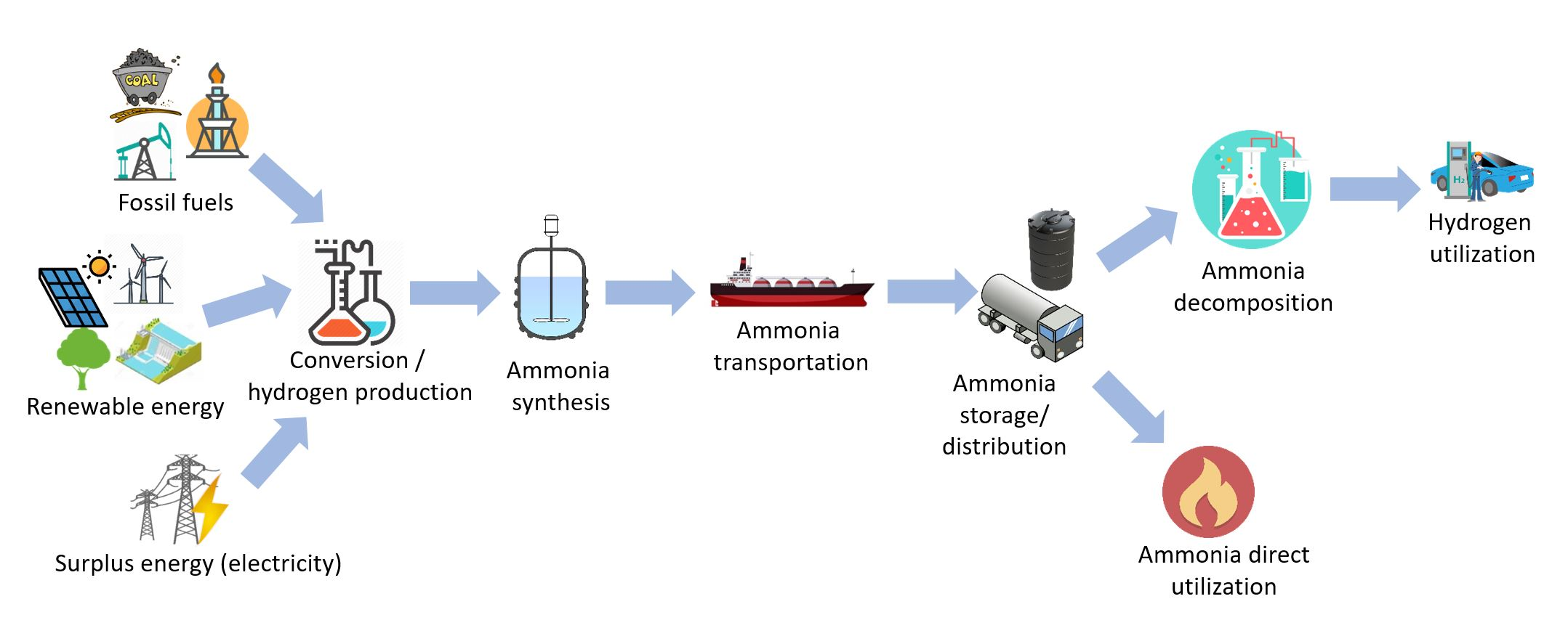
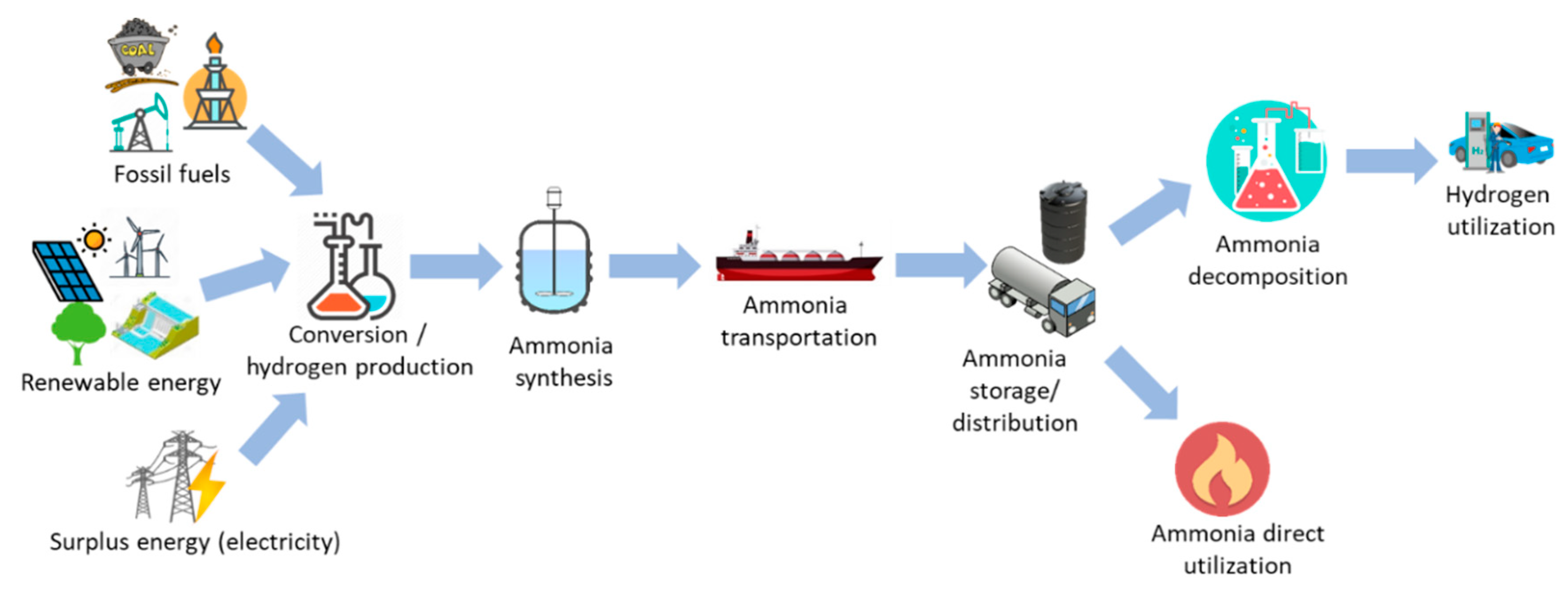
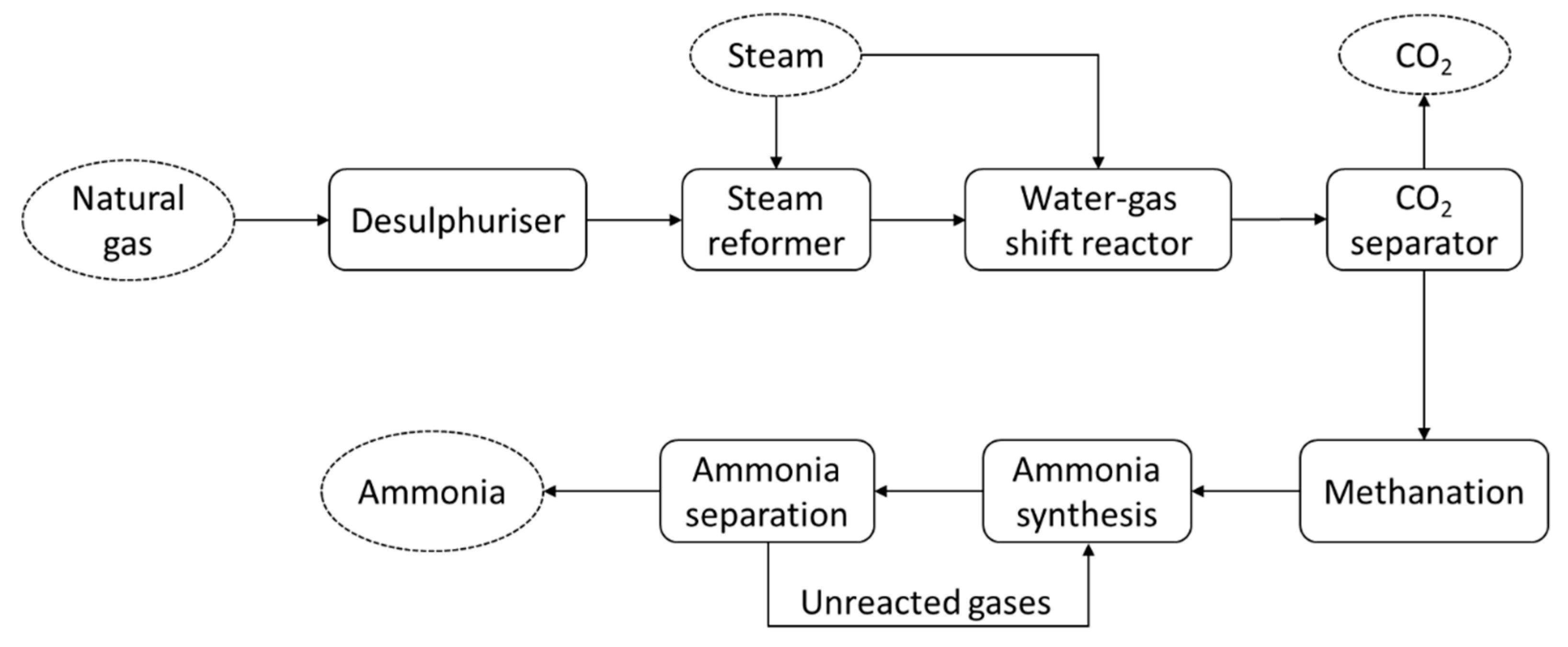
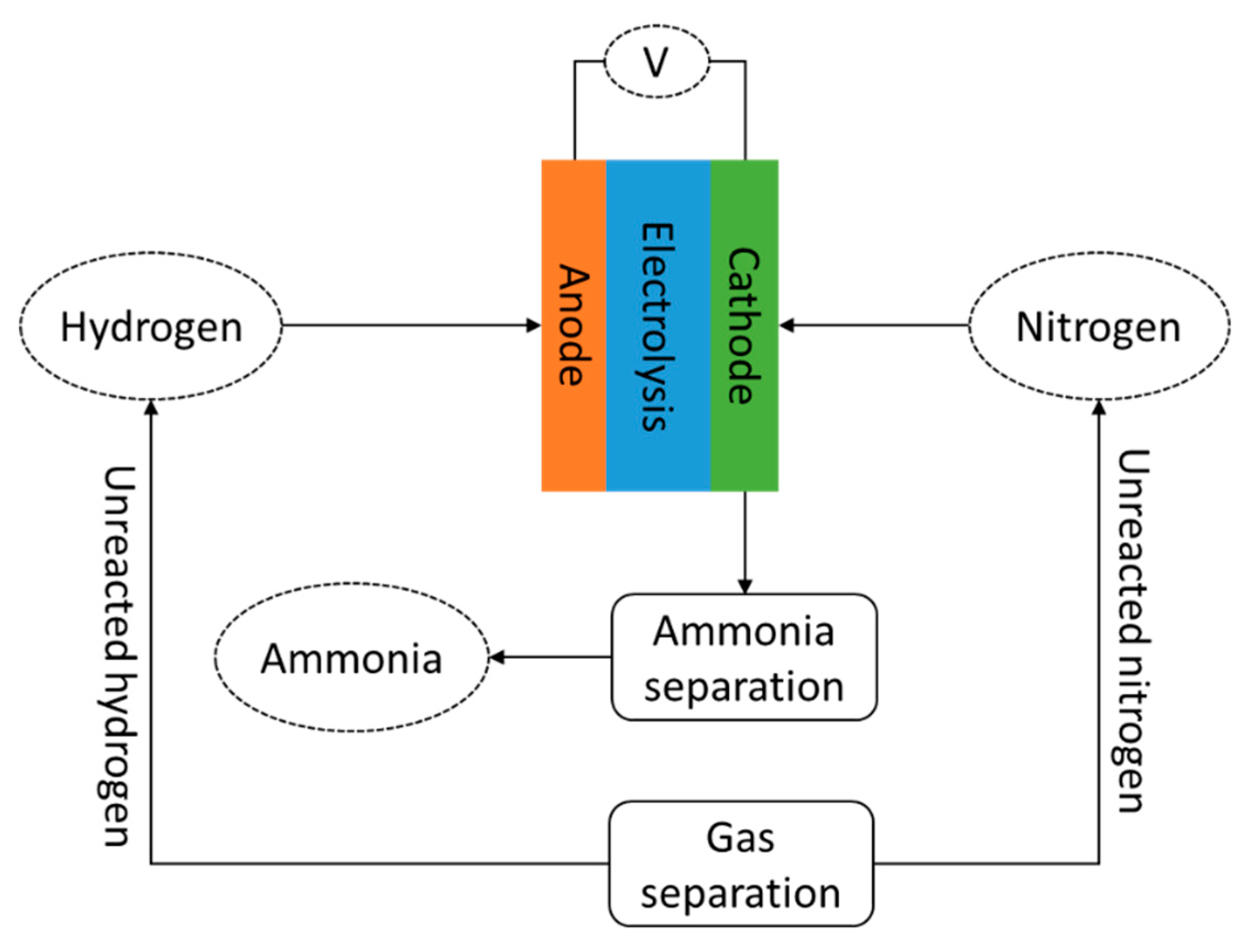
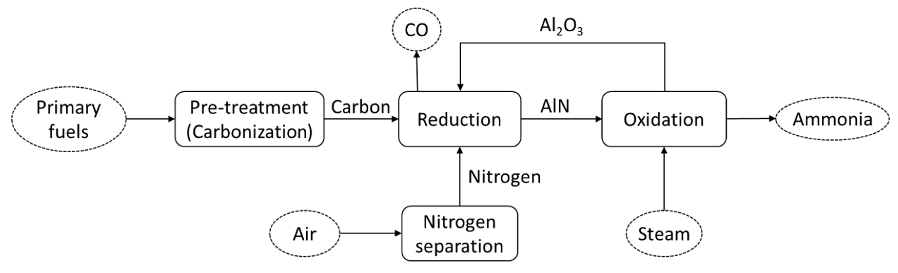
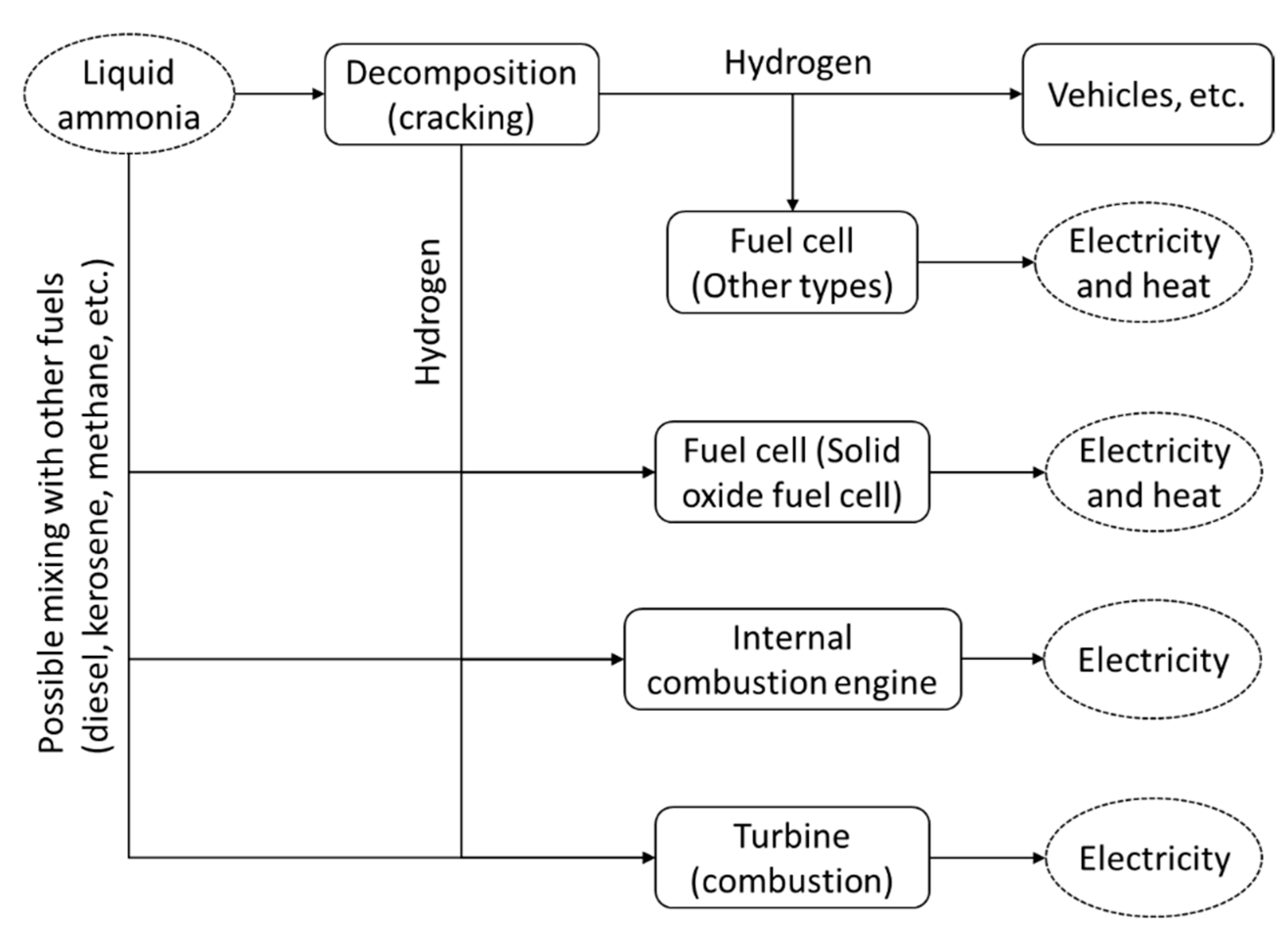
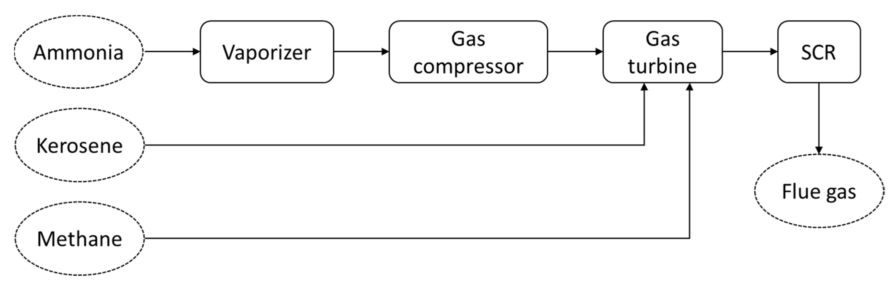
| Properties | Unit | Value |
|---|---|---|
| Molar mass | g/mol | 17.031 |
| Density at STP | kg/m3 | 0.769 |
| Melting point | °C | −77.73 |
| Boiling point at 100 kPa | °C | −33.4 |
| Vapor pressure at 20 °C | kPa | 858 |
| Heat of evaporation | MJ/kg | 1.371 |
| Auto ignition temperature | °C | 650 |
| Critical temperature | °C | 132.4 |
| Critical pressure | MPa | 11.28 |
| Viscosity at 25 °C | µPa·s | 10.07 |
| Heat capacity at constant pressure (101.325 kPa, 15 °C) | kJ/mol·°C | 0.037 |
| Heat capacity at constant volume (101.325 kPa, 15 °C) | kJ/mol·°C | 0.028 |
| Heat of combustion | MJ/L | 11.2 |
| Thermal conductivity | mW/m·°C | 22.19 |
| Critical density | g/mL | 0.24 |
| Condensation pressure at 25 °C | MPa | 0.99 |
| Flammability limit (equivalence ratio) | - | 0.63–1.4 |
| Adiabatic flame temperature | °C | 1800 |
| Max. laminar burning velocity | m/s | 0.07 |
Table 2.
Characteristics comparison of compressed hydrogen, liquid hydrogen, methanol and liquid ammonia [36,38,39].
| Properties | Unit | Compressed Hydrogen | Liquid Hydrogen | Methanol | Liquid Ammonia |
|---|---|---|---|---|---|
| Storage method | - | Compression | Liquefaction | Ambient | Liquefaction |
| Temperature | °C | 25 (room) | −252.9 | 25 (room) | 25 (room) |
| Storage pressure | MPa | 69 | 0.1 | 0.1 | 0.99 |
| Density | kg/m3 | 39 | 70.8 | 792 | 600 |
| Explosive limit in air | %vol | 4–75 | 4–75 | 6.7–36 | 15–28 |
| Gravimetric energy density (LHV) | MJ/kg | 120 | 120 | 20.1 | 18.6 |
| Volumetric energy density (LHV) | MJ/L | 4.5 | 8.49 | 15.8 | 12.7 |
| Gravimetric hydrogen content | wt% | 100 | 100 | 12.5 | 17.8 |
| Volumetric hydrogen content | kg-H2/m3 | 42.2 | 70.8 | 99 | 121 |
| Hydrogen release | - | Pressure release | Evaporation | Catalytic decomposition T > 200 °C | Catalytic decomposition T > 400 °C |
| Energy to extract hydrogen | kJ/mol-H2 | - | 0.907 | 16.3 | 30.6 |
© 2020 by the authors. Licensee MDPI, Basel, Switzerland. This article is an open access article distributed under the terms and conditions of the Creative Commons Attribution (CC BY) license (http://creativecommons.org/licenses/by/4.0/).
Share and Cite
MDPI and ACS Style
Aziz, M.; Wijayanta, A.T.; Nandiyanto, A.B.D. Ammonia as Effective Hydrogen Storage: A Review on Production, Storage and Utilization. Energies 2020, 13, 3062. https://doi.org/10.3390/en13123062
AMA Style
Aziz M, Wijayanta AT, Nandiyanto ABD. Ammonia as Effective Hydrogen Storage: A Review on Production, Storage and Utilization. Energies. 2020; 13(12):3062. https://doi.org/10.3390/en13123062
Chicago/Turabian StyleAziz, Muhammad, Agung Tri Wijayanta, and Asep Bayu Dani Nandiyanto. 2020. "Ammonia as Effective Hydrogen Storage: A Review on Production, Storage and Utilization" Energies 13, no. 12: 3062. https://doi.org/10.3390/en13123062
Note that from the first issue of 2016, this journal uses article numbers instead of page numbers. See further details here.